Data Transfer Protocol Designs Generated by SAT
Second example: Two Rail Coding The Cambridge Ring and the Inmos Transputer network both used a pair of binary signals between nodes, but were tolerant to the wires being inverted and/or crossed. The seven possible perturbations to the channel can be expressed by adding three free variables as shown. We created a second, similar protocol design example by adding this second path, but without changing the overall specification.
  protocol TWORAIL_PROTOCOL
  {

    node bool: din, dout;

    // Reset Logic
	node bool: reset_0, reset_1, resetting;
	initial reset_0 == 1 && reset_1 == 1;
	X(reset_0) := 0;
	X(reset_1) := reset_0;
	resetting := reset_0 | reset_1;

  //--------------------------
  // Transmitter encoder
  // Encoder state
    node bool: s0, tx1, tx2;

     X(tx1) := XFUN("xtx1", din, tx1, s0);
     X(tx2) := XFUN("xtx2", din, tx2, s0);
     X(s0) := XFUN("xtxs", din, tx1, tx2, s0);


  // Transmitter Constraints - we require a change on at least one of the
  // two lines.
  // Fails if we request an AND in the next line.
  always tx1 != X(tx1) \/ tx2 != X(tx2);


  //--------------------------
  // Channel Model
  // This two wire channel may be permanently
  // swapped and/or inverted in one half or the other.
   node bool: rx1, rx2, ch_inv1, ch_inv2, ch_swap;

   X(ch_inv1) := ch_inv1;  // These assigns mean that
   X(ch_inv2) := ch_inv2;  // the initial value of this variable is not known
   X(ch_swap) := ch_swap;  // but that it will not change.

   rx1 := ((ch_swap) ? tx1:tx2) ^ ch_inv1;
   rx2 := ((ch_swap) ? tx2:tx1) ^ ch_inv2;

   //--------------------------
   // Receiver decoder
   node bool: srx;
   X(dout) := XFUN("xDOUT", rx1, rx2, dout, srx);
   X(srx)  := XFUN("xSRX", rx1, rx2, dout, srx);

   node bool: match0, match1, match2, match3, match4, working;

   match1 := X(dout,1) == din;
   match2 := X(dout,2) == din;
   match3 := X(dout,3) == din;

   // By selecting a value for xdel, the tool can decide how much pipeline delay
   // in the coder+decoder.
   node bool: xdel0, xdel1;

   working := (xdel1) ? match3: (xdel0) ? match1 : match2;

   always resetting \/ working;

  }


  // Now we have a pair of system structures, one that describes the encoder
  // and one that describes the decoder.  Both conform to an exact refinement of the protocol
  // loosely specified above.


  section TWORAIL_ENCODER
  {
     node bool in : din;
     node bool out protocol TWORAIL: tx1, tx2;
  }

  section TWORAIL_DECODER
  {
     node bool in protocol TWORAIL: tx1, tx2;
     node bool dout : dout;
  }
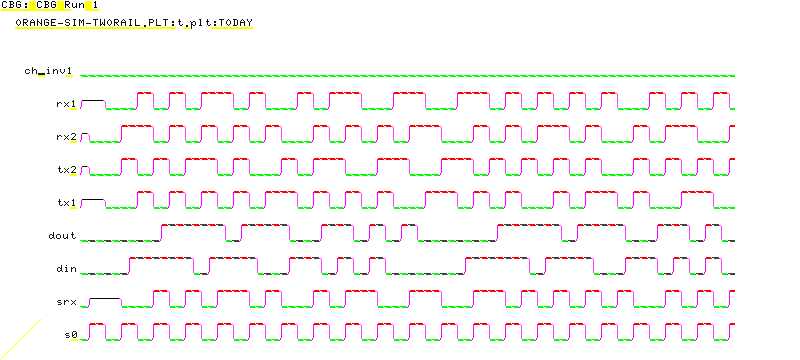
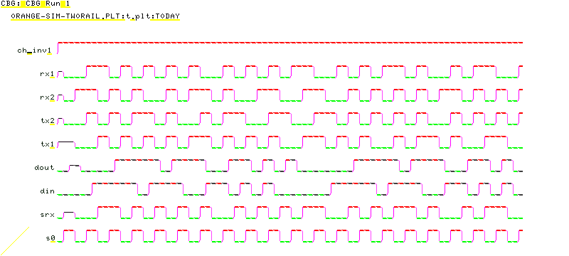
Output from the compilationThe following circuit was generated by chaff. Looking at this carefully, we can see it has chosen to alternate tx1 on every baud interval and to NRZI encode the data on tx2. However, cleverly, the receiver is insensitive to the interchange of tx1 and tx2. We also see that it did not chose to use the available transmitter buried state bit s0.
Design is as follows:
Report on X(tx1)
     It was COND(tx1, s0, true)

Report on X(tx2)
     It was COND(din, ~tx2, tx2&~s0)

Report on X(s0)
     It was false

Report on X(ch_inv1)
     It was ch_inv1

Report on X(ch_inv2)
     It was ch_inv2

Report on X(ch_swap)
     It was ch_swap

Report on X(rx1)
     It was ~(COND(ch_swap, tx1, tx2))&ch_inv1|(COND(ch_swap, tx1, tx2))&~ch_inv1

Report on X(rx2)
     It was ~(COND(ch_swap, tx2, tx1))&ch_inv2|(COND(ch_swap, tx2, tx1))&~ch_inv2

Report on X(srx)
     It was COND(rx1, COND(rx2, ~srx, true), true)

Report on X(sry)
     It was COND(rx1, rx2&~srx, ~srx)

Report on dout
     It was COND(rx1, COND(rx2, srx|~sry, COND(srx, ~sry, sry)),
                      COND(rx2, srx&sry, COND(srx, false, ~sry)))

Report on match1
     It was X(dout)&din|~X(dout)&~din

Report on match2
     It was X(dout,2)&din|~X(dout,2)&~din

Report on match3
     It was X(dout,3)&din|~X(dout,3)&~din

Report on working
     It was match2

Report on X(dout)
     It was COND(X(rx1), COND(X(rx2), X(srx)|~X(sry),
      COND(X(srx), ~X(sry), X(sry))), COND(X(rx2), X(srx)&X(sry),
      COND(X(srx), false, ~X(sry))))

Report on X(din)
     It was FUTdin_1

Was the design. 32 equations in result
Successful Completion.
Here is a simulation run generated when the channel is not crossed or inverted  Here is a simulation run generated when it is crossed and half inverted  The nets marked prb are a prbs generator used in the testbench to create some stimulus for din. The circuit generated by a run of the tool on this specification has been drawn out by hand for the white paper. Another ExamplePlease see GPIB to Centronix Example. |