Hardware and Software Interface Synthesis for GPIB using H2.
The specification IS the design!
|
By today's standards, the IEEE-488 bus is quite simple. Also known as
HPIB and GPIB, it is an IEEE standard that connects a number of
devices in the local area using sixteen parallel wires (plus
grounds). Although USB is a more-recent replacement technology, GPIB is
still widely used in industrial control, and it provides fine material
for the following examples. An overview can be found in Mullard
Technical Comms, No 138, April 78.
Around 20 years ago, DJG implemented a number of devices that connected to each other using IEEE-488. The devices were implemented using discrete TTL chips and small subroutines on 6800's and the like. These designs are now all be generated automatically as seeds for our HPRLS project, starting from a small amount of declarative specification of the protocols to be connected. The designs included:
An interesting feature of GPIB is its ability for a controller to set up a third party multicast from a single talker to multiple listeners in parallel. The relatively complex 3-wire handshake using DAV, NRFD and NDAC exists to implement this facility, and hence the bus is not totally trivial. The general Organgepath approach synthesises the required interface hardware and driver software. It needs a definition of the resources available for communication and any mixture of the constraints on the protocols used and code fragments. In the example presented here, we have manually-coded, complete, formal specifications of the interface protocols, and we synthesise interface automata from pairs of these. Formal Definition of the BusHere we manually code a formal definition of IEEE-488 using our toy H2 specification language. The physical resources are 8 data wires and 8 control wires. These are connected in parallel to every device. Each net implements a wired-nor function, meaning that all stations can read the current value of every wire and this is a logic zero if any device is pulling it low. There is a known, finite, maximum skew between the wires, and a bundled-data asynchronous guard protocol is used, that delays the guard net assertion until all wires have settled under worst-case skew. The bus is defined to have one fixed controller, and for any transaction, one active talker and some number of active listeners. The controller can be the current talker or one of the current listeners. The bus specification defines that certain wires are always driven by the controller whereas others are driven by the talker and others are a wired-nor function of the listener outputs. We define the bus as a union of the functions unique to the controller and the remainder, concerned with data transfer between talker and listener:
interface GPIB
{
   GPIB_M;    // Controller part
   GPIB_DC;   // Data transfer part
}

interface GPIB_SLAVE
{
  protocol gpib_slave;

  forward:
   node out !ren;     // Remote enable
   node out !atn;     // Attentions
   node out !ifc;     // Interface clear
   node in  !srq;     // Service Request

}

interface GPIB_DC()
{
  neutral:

  forward:
     node out [7:0] data;  // The data
     node out !dav;        // Data valid.
     node out !eoi;        // Asserted for last bit of data
     node in !ndac;        // Negative data acknowledge
     node in !nnrf;        // Not ready for data

     protocol gpib_talker_hs;

  reverse:

     protocol gpib_acceptor_hs;

}
The built-in node types include in, out, and inout, but user-defined interfaces can also be used as nodes. The built-in nodes range over a single bit or a scalar. Arrays, sets and lists might be added as built-in types in the future. H2 provides various forms of specification. In this example, we demonstrate these by using different forms for different parts of the protocol, but a real user generally be more consistent across his specification and so use fewer forms. Listener Side ProtocolUsing the statemachine specification form, a named state is introduced with a colon. Here we only use one named state, called 'start'. The other states are anonymous and their existence is inferred from the presence of wait commands and the blocking write to channel rx.
// IEEE-488 listener-side protocol specified using a state machine
protocol gpib_acceptor_hs()
{
  statemachine(ach)
   {
     start:
      ndac = 1;
      wait (dav);

      nrfd = 1; ndac = 0;

      rx = ?d8;  // Read the input channel

      wait(!dav);

      nrfd = 0;
     goto start;
   }
}
Talker Side ProtocolThe talker_hs implements bundled-data guarding with a synchd() command. This models the bus settling delay.
protocol talker_hs
{
  statemachine(ach)
   {
     start:
      wait(nrfd);
      d8!tx
      synchd(1);
      dav = 0;
      wait(ndac);
      d8!X; dav = 1;   // X here denotes don't care
     goto start;
   }
}
Controller/Slave ProtocolTo illustrate yet a third form of protocol specification, we specify the slave protocol using just a state variable and a set of assertions. The controller protocol is the slave protocol with the signals reversed. Our specification instantiates the talker and listner sub-protocols, which is not difficult to do inside a tool that converts the statecharts and regular expressions into declarations. However, our ambition for larger designs is not to loose the behavioural hints from these more direct input forms at the point when we are assembling components.
protocol gpib_slave
{
   statevar s enum { idle, talker, listener };

   always ~ifc => s == idle;

   always
      (ifc & ~atn & ~dav) &&  d8[7:5]==1 && d8[4:0]==Addr => s == talker
   /\ (ifc & ~atn & ~dav) && d8[7:5]==2 && d8[4:0]==Addr => s == listner
   /\ (ifc & ~atn & ~dav) && d8[7:5]==1 && d8[4:0]==31 => s == idle
   /\ (ifc & ~atn & ~dav) && d8[7:5]==2 && d8[4:0]==31 => s == idle;

   always talker => talker_hs /\ listner => listner_hs;

}
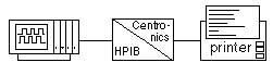
Centronix Parallel PortSince we are synthesising bus bridges, we also require formal specifications for the attached interfaces. In this section we define Centronix. Centronix is a conventional bundled-data
four-phase handshake with an additional
busy signal to provide flow control backpressure. We could specify
the centronix protocol using separate sender and receiver state charts
but to illustrate mixing of methodologies, we use an extended regular
expression.
The protocol specification is an assertion of a regular expression.
This is taken to mean that the idle and starting state of the interface
is the starting state for evaluating the regular expression and that
it will loop back to this point immediately on after exiting.
The use of the = symbol in this infix form creates a quick assign.
For the forward direction of the interface, d8=tx means d8!tx. This is a write
to a channel, which for a set of simple wires, such as d8, means to set them to
this value until a d8!X occurs, which means they are don't care from then on.
For the reverse direction of the interface, d8=tx will cause a read from channel d8.
A channel is currently another word for a node, but eventually we can nest all of these
concepts.
The centronix behavioural model can be synthesised from nothing more than the following
method declarations:
To create a simplex bus bridge between the two protocols we make the following
structural composition that instantiates the two interfaces and then
we need to plumb the rx channel of the GPIB to the tx channel of the
Centronix and we need to set a GPIB listner address (as set on the DIL
switches in the real design below). In this subsection we are only handling
centronix output, so the talker side of the GPIB protocol will not be
used, despite being present in the tool.
Note that the two interfaces are not connected to each other via their
I/O nodes: these are exposed for outside connection of devices to the bus bridge.
Instead, our tool wires the two interfaces to each other by creating
an internal datapath and handshake as a result of the connect directive.
There is no constraint on the delay of the interface (it could include a large
FIFO) but order conservation is implied.
The name `SIMPLEX_BUSBRIDGE' is passed to the H2 tool on its command line
as the root to work from. The modifier forward is added to the instance
of the GPIB, but this is the default direction anyway.
Note that the dot symbol is used for access to components of a structure as well as
sequencing in regular expressions, depending on context.
We extend this example by adding an additional input, designed to be connected
to a manual switch, that will take the printer offline. It will do this by causing
each interface not to leave its idle state after it next enters it.
TODO ... where is this ?
TODO ... where is this ?
We extend this example by adding a second centronix port of the other direction
and connecting this to the talker function of the GPIB. Owing to the intrinsic nature
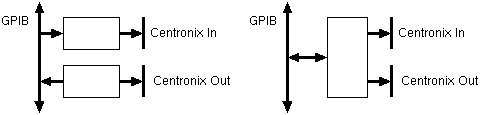
of GPIB, the resulting design can be implemented in one of two ways:
In the left-hand way, we make two runs of the tool to create two separate
bus bridges that can be connected to the bus. In the right-hand way, one run of
the tool generates a single composite system.
An illustration of a contemporary commercial product.
|
|
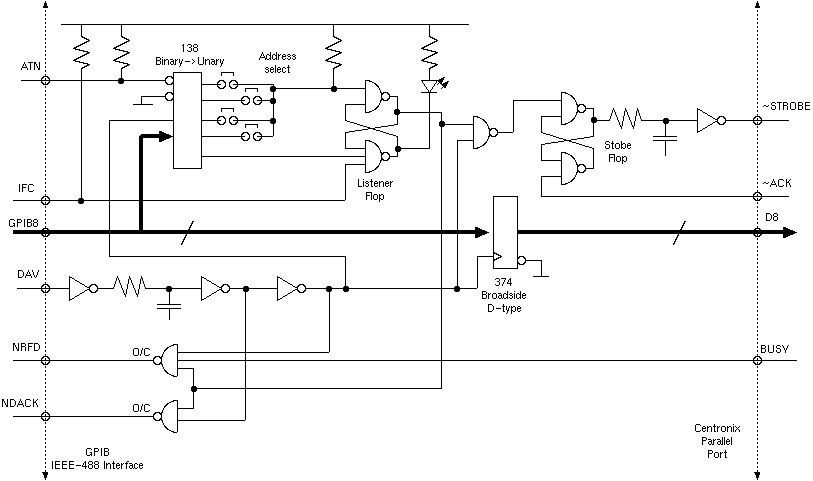
Old DJG DesignThe schematic shows the core circuit of an implementation of a simplex GPIB to Centronix parallel port converter unit that I made in the late seventies. The design has a number of features: The circuit operates as follows. When the unit is idle or after being reset with the IFC interface clear signal, the listner flop is clear. When ATN is asserted low and the correct address and command are received, the listner flop is set. We remain in listener mode until an unlisten command. While in listner mode, we execute the acceptor handshake, by alternately driving NRFD and NDAC low in response to the DAV signal. The DAV signal is delayed in the first delay stage in case it should arrive early, although actually it is the talker's duty to delay DAV with respect to the data. The Centronix handshake is implemented with a second RS-latch and a second delay unit delays the assertion of the strobe signal until the data has settled. DOT DOT DOT - under construction - last modified 16 Jul 2003 but being finished finally now (Mar 2007) ... well maybe not! (C) January 2003 DJ Greaves. Home. |