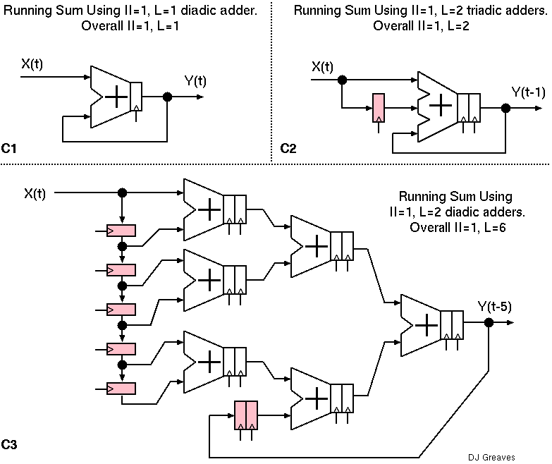
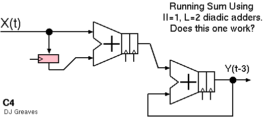
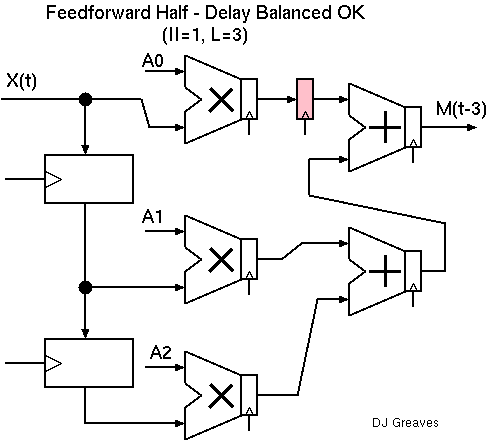
Various circuits that perform a running sum.
The high-level expression of a basic block may contain some number of arithmetic operators, such as 9 additions and 10 multiplies for a 10-stage FIR filter. But we may wish to render this in hardware using fewer FUs. For instance, to do this in 3 clock cycles, 3 adders and 4 multipliers are nominally sufficient as this will meet the required basic operations-per-second budget.
But the FUs will often be pipelined and the output from one may not be ready for the input to the next in time.
If data is streaming, then the problem should be solvable with the minimal number of FUs given sufficient pipelining. The pipeline initiation interval (II) will be 3, but the latency larger than 3.
Streaming hardware designs with low II are suprisingly complex and difficult to find when the ALUs available are heavily pipelined. Floating point ALUs tend to have multi-cycle delay (latency of four to six cycles is commmon for add and multiply in FPGA).
A scheduller program will solve the problem of making a static mapping of operations to FUs. It can be phrased nicely as an ILP problem (Sittel/Koch `ILP-based Modulo Scheduling and Binding for Register Minimization' FPL2018). The result is called a modulo schedule. The modulo basis will be the II, 3. Once the schedule is computed it is then fairly simple to render a sequencer circuit and additional holding registers as needed.
A design with initiation interval of one is said to be fully-pipelined whereas a higher initiation interval can generally be supported with less silicon area using modulo schedulling.
Example 1: The Running Sum
If the adder has unity latency the running sum example is simple. For a two-cycle adder with three inputs, it is also trivial. The minimal circuit for latency-of-two adders with only two inputs is surprisingly complex.
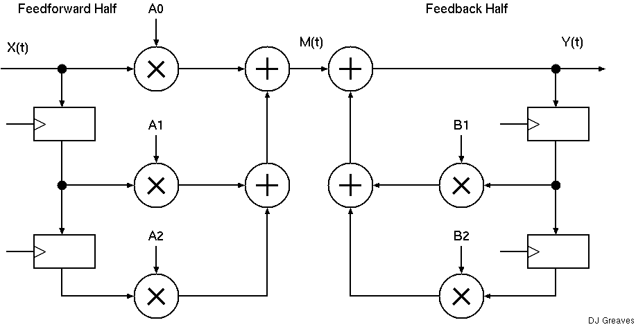
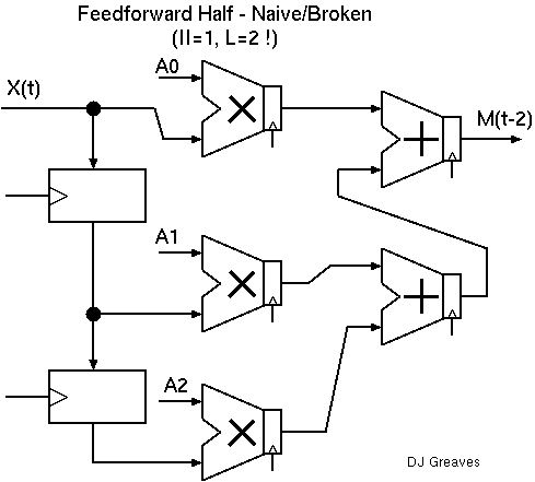
Example 2: Bi-quad Filter Element
Rearranging the operator association can greatly help with producing a good schedule.
| 29: (C) 2008-18, DJ Greaves, University of Cambridge, Computer Laboratory. |