https://www.cl.cam.ac.uk/~djg11/pubs/Wireless-World-1986-12-DJ-Greaves-Digital-Echo-Unit/
Article PDF (1.5 pages).
Despite its simplicity, this compact sound delay unit gives a repeating echo with a half-second period and good fidelity. Input and output are at line level and current consumption is about 65mA.
Two controls are provided; the delay-time control gives the period between echos and the recirculate control sets the fraction of the delayed signal fed back to give multiple echos. The unit's single 64K-bit ram i.c. gives a comparable memory to echo units with eight-bit converters and 8K-byte of storage.
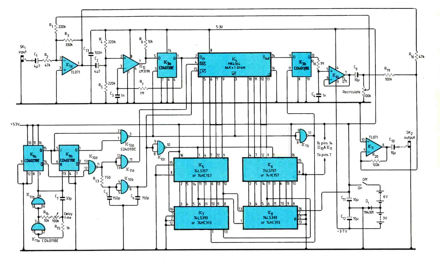
Simplicity is achieved through use of a type of digital/analogue conversion known as delta-sigma modulation. As well as requiring few components, this type of converter produces only one output bit and does not suffer from the same kind of clipping distortion that occurs when conventional converters are overdriven. Instead, over-large signals cause slew rate distortion which is far less noticeable to the ear. This means that far less headroom needs to be allowed for sound peaks when setting up and the overall signal- to-noise ratio is correspondingly increased. Each memory location is selected in turn; on each selection, old contents are read and new data is written. Time taken to cycle round all 65536 locations is the echo or delay time.
Counter IC9 is constantly clocked at around 5OOkHz by the oscillator formed by IClla,b. This counter is used as a sequencer to control the rest of the digital electronics. It counts through four phases 00, 10, 01 and 11, performing the following actions. In phase00, ICI1, goes low, incrementing the main address counter IC7,8. During the rest ofthis state, the address counter ripples through and settles down.
During phase 10, ICIid pulls the memory its line low. This causes the memory to latch the low eight bits of the address counter and takes care of memory refresh. At about 3Ons after RAs, the signal propagates through the delay section around IC10b. This causes data selectors IC5,6 to switch and present the high-order eight bits of data to the memory. At the same time, CAS is pulled low. Phase 01 causes the memory device to recall its stored information for the current address and put it on pin 14. This data is latched into IC3b on the transition to the next state.
The memory's WE line is held low during phase 11, causing data from IC3a to over-write the data that has just been read out. At the end of the state, CAS, RAS and WE all go high and IC3a is clocked to fetch a new bit from the input.
I have built the unit into an existing commercial mixing desk between the echo-send and echo-return connections. It is wired so that it switches out when an external effects unit is plugged in. However the circuit can be used as a stand-alone unit without modification.
Using battery power only a single-pole switch is needed. When the circuit is switched off, the diode prevents power drain from the-3V battery.
D.J. Greaves
St John's College
Cambridge
December 1986.