Binary, Hexadecimal and Other Number Systems
Positive Integers and Bases
What is 7+3? In most contexts you would answer “10”, but really the question is underspecified since the base of the numbers was not given. By base we mean the number of digits in the number system. Answering 10 just assumed we were using base-10 (decimal), which uses the ten digits 0–9. In general, for any k-digit decimal number \(N_{10}=a_{k-1}a_{k-2}...a_1a_0\), we have:
\[N_{10} = \sum_0^{k-1}{a_i10^i} = a_o+a_1.10^1+a_2.10^2+...\]
Why 10?
It’s an interesting question why we favour base-10 in our society. The most oft-quoted answer is that we have ten digits on two hands, but there isn’t any particular evidence for this. All we know is that many early cultures seem to have used decimal systems.
So \(123=3+2\times10^1+1\times10^2\). For a general base, \(b\), this easily extends:
\[N_{b} = \sum_0^{k-1}{a_ib^i} = a_0+a_1.b+a_2.b^2+...\]
Base-2 (binary, \(b=2\)), with the binary digits (bits) 0 and 1 only, is also common. In fact, there is something ‘special’ about binary since you cannot communicate information with fewer than two symbols (for clarification the absence of any symbol is itself a signal). So, binary is the smallest number of useful symbols for encoding information, and hence the bit is used as the unit of information.
Binary is also the easiest to implement in computer hardware since each bit can be represented by a switch: on or off. So vast majority of computers are built on it. Usually we like our numbers to be displayed in decimal, however, which is mildly irritating because ten can’t be represented efficiently with an integer number of bits (see questions).
One of the downsides to binary is that relatively small numbers require lots of digits that are harder for the human brain to recall and handle. e.g. \(1234_{10}=10011010010_2\). Instead, we prefer to use higher bases.
In computing, we prefer power-of-two bases, since these correspond to straightforward partitioning of a binary number. For example, Base-8 (octal) is useful because it’s the closest power-of-two to 10. It uses the symbols 0–7 inclusive and effectively groups a binary number into 3-bit chunks:
\[1234_{10}=10011010010_2=010\:011\:010\:010_2=2322_{8}.\]
Even more common is to group them into chunks of four to get a base-16 representation (hexadecimal or just “hex”). Here we have a problem since we need 16 symbols, but only have 10 in our vocabulary (0 to 9). We use the alphabet to extend our symbols, which now range from 0–9 followed by A–F (i.e. \(10_{10}=A_{16}\), \(15_{10}=F_{16}\)). So now:
\[1234_{10}=10011010010_2=0100\:1101\:0010_2=4D2_{16}\]
Because hex is so commonly used and subscripts aren’t easy to add in code, we preface a hex number with “0x”, so \(4D2_{16}\) is 0x4D2. For some reason there isn’t a uniformly-adopted prefix for octal—you may see \(123_8\) written as \(0o123\), \(0123\), \(o123\), \(q123\), or something else entirely! Thankfully, hex is the preferred choice these days.
Bits, Bytes, Words, etc
When working with computers, you come across a variety of units for data. The bit (BInary digiT) is probably the only one that is completely unambiguous: it is either 0 or 1, and we know that it represents a fundamental unit of data.
A byte was historically unstandardised, and was the number of bits used to represent a single character (i.e. letter) on the system in use. However, there is now a de-facto standard of 8 bits in a byte and it is common for a byte to be assumed to be 8 bits. As such, it can take values between 0 and 255 or 0x00 to 0xFF in hex (inclusive). May official texts prefer the use of ‘octet’ to avoid any ambiguity, but we’ll stick with byte.
A nibble or nybble is usually defined as half a byte, which is de-facto 4-bits or one hex digit.
A word is platform-specific and is the natural unit of data in the processor. It is often (although not always) the number of bits a processor can transfer or manipulate in a single instruction (see the How Computers Work material). Most desktop machines use either 32-bit or 64-bit words; some tiny embedded computer systems will use 8-bit or 16-bit words.
We often deal with large values and need prefix-multipliers. This should be straightforward except that SI multipliers (micro-, kilo-, mega-, etc.) were designed for base-10, not base-2. This led to some confusion. For example, should one kilobyte represent 1,000 bytes or 1,024 (\(2^{10}\)) bytes? To resolve this problem the IEC defined two variants of the SI multipliers; for example kilo- and kibi-, mega and mebi-, and giga- and gibi- are defined as follows:
| Name | Suffix | Size (bytes) |
|---|---|---|
| kilobyte | KB | 1,000 |
| kibibyte | KiB | 1,024 |
| megabyte | MB | 1,000,000 |
| mebibyte | MiB | 1,048,576 |
| gigabyte | GB | 1,000,000,000 |
| gibibyte | GiB | 1,073,741,824 |
Nevertheless it is often the case that kilo-, mega-, giga-, etc. are used when kibi-, mebi-, gibi- are, in fact the correct terms, so this is something to be aware of.
Most and Least Significant Bits (MSB, LSB)
We often refer to the Most Significant Bit (MSB) and Least Significant Bit (LSB) when talking about binary numbers. The MSB means the bit associated with the highest power of two (i.e. leftmost bit), whilst the LSB refers to the rightmost bit. In some contexts the MSB refers to to the most significant non-zero bit. So:
| Number | LSB | MSB |
|---|---|---|
| 10010 | 0 | 1 |
| 010 | 0 | 1 (ignore leading zeroes) |
| 111 | 1 | 1 |
| 1 | 1 | 1 |
| 0 | 0 | 0 |
Binary Addition and Subtraction
The binary addition algorithm is an easier version of the standard decimal addition algorithm you all did at school. Add the bits from right-to-left (LSB to MSB), carrying over wherever necessary. There are just four rules:
 0+0=0
 0+1=1
 1+0=1
 1+1=0, carry 1
Here’s a worked example:
| - | - | - | - | ||
|---|---|---|---|---|---|
| 1 | 0 | 1 | 1 | ||
| + | 1 | 1 | 0 | 1 | |
| - | - | - | - | - |
| - | - | - | 1 | ||
|---|---|---|---|---|---|
| 1 | 0 | 1 | 1 | ||
| + | 1 | 1 | 0 | 1 | |
| - | - | - | - | 0 |
| - | - | 1 | 1 | ||
|---|---|---|---|---|---|
| 1 | 0 | 1 | 1 | ||
| + | 1 | 1 | 0 | 1 | |
| - | - | - | 0 | 0 |
| - | 1 | 1 | 1 | ||
|---|---|---|---|---|---|
| 1 | 0 | 1 | 1 | ||
| + | 1 | 1 | 0 | 1 | |
| - | - | 0 | 0 | 0 |
| 1 | 1 | 1 | 1 | ||
|---|---|---|---|---|---|
| 1 | 0 | 1 | 1 | ||
| + | 1 | 1 | 0 | 1 | |
| - | 0 | 0 | 0 | 0 |
| 1 | 1 | 1 | 1 | ||
|---|---|---|---|---|---|
| 1 | 0 | 1 | 1 | ||
| + | 1 | 1 | 0 | 1 | |
| 1 | 1 | 0 | 0 | 0 |
To do subtraction, you were probably taught to ‘borrow’ from the left where necessary. We do exactly the same in binary subtraction. When you came across \((a-b)\) and \(a<b\) (i.e. a negative result) you were most likely taught to compute \((b-a)\) and add a negative sign. This works in binary too, although representing negative numbers in a machine ends up being more complicated, as we will see presently. For now just make sure you can perform addition and subtraction in binary on paper.
Integer Overflow
We’ve glossed over an important point: computers work on small, well-defined pieces of memory (registers - see the How Computers Work primer). If, for example, those registers are 32 bits long and our addition results in a 33 bit number, we have a problem since we can’t squeeze it into the answer slot. So what happens?
The answer is that the number overflows and we lose that 33rd bit. If we work on a more tractable three-bit number we might have:
| 1 | 1 | 1 | ||
|---|---|---|---|---|
| 1 | 0 | 1 | ||
| + | 1 | 1 | 1 | |
| 1 | 1 | 0 | 0 |
However, the computer only has three bits so it loses the MSB and the answer left is 100. We can at least spot this happening by checking the carry flag (a special piece of hardware used to record if overflow occurred). However, on most computer systems, this problem is silent: if you don’t check the carry flag, you won’t be warned that something went wrong and computation will continue with the incorrect value!
The behaviour of overflow gives rise to clock arithmetic or modulo arithmetic. Imagine a clock face with all zeroes at 12-o-clock. Moving clockwise, draw all the bit patterns representable by the number of bits you have in ascending binary order (black numbers below). Then add the labels for decimal representations of those numbers (in blue below). For three-bit numbers we get:
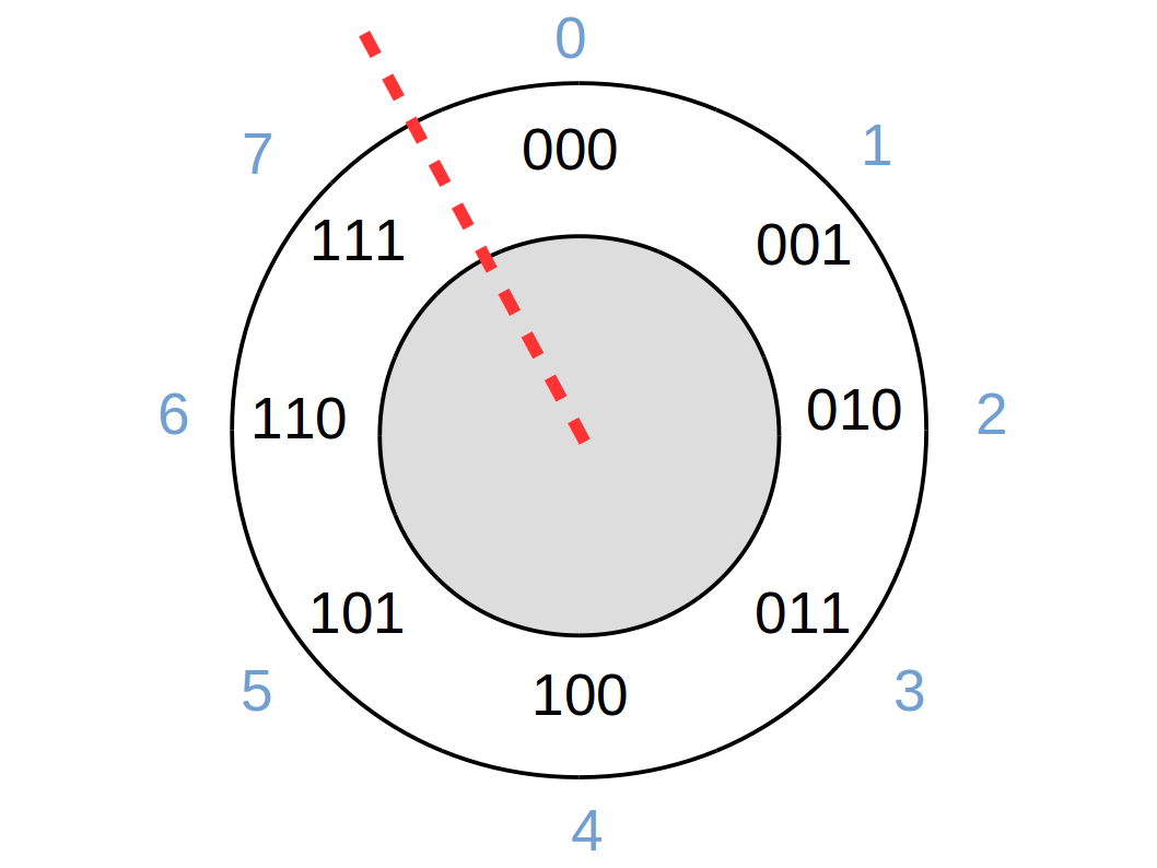
The red line marks a discontinuity. For example, if we add one on to seven (i.e. 7 + 1) then we start at position seven and move clockwise around the clock by one position, giving the result of zero (i.e. 7 + 1 = 0) and not eight. Mathematically we would write (7 + 1) mod 8, where “mod X” or modulo X is the remainder after dividing the answer by X.
A useful way to view our arithmetic circuits is that they move us clockwise around the clock (addition) or anti-clockwise (subtraction).
Negative Integers
So how do we handle negative numbers? There are three common approaches: sign-magnitude, one’s-complement, and two’s-complement. We almost always end up using two’s complement but to understand why, it is helpful to look at the others first.
Sign-Magnitude
This is the obvious way: make the MSB (leftmost bit) signal whether it’s a negative number or not. So 1011 would be read as 1-011, or -3. More examples:
- 0101 is 5
- 1101 is -5
- 1111 is -7
This appears simple and easy to work with. In terms of our clock face we have:
In this representation, we can see that any computer hardware designed for unsigned numbers does not work here: the negative numbers increase anti-clockwise, while the positives increase clockwise as before. In addition, we have two representations for zero: 0000 (zero) and 1000 (minus zero!). So if we go for this representation, we’ll need specialist circuitry to handle negatives. It turns out we can do better, as we will see.
One’s Complement
An alternative approach to represent a negative is to use the one’s complement of the positive, To form the one’s complement you simply flip all of the bits. So, 010 (+2) becomes 101 which is taken to represent -2. So, to determine the value of a ones complement numbers first check the MSB. If the MSB is 0, then this is a positive number and its values can be read directly as a binary number; otherwise the number is negative so flip the remaining bits before interpreting as a binary number.
Drawing the clock face representation:
This is a little better: Moving clockwise increases the number unless you cross the one discontinuity. Sadly the double-zero issue remains. Again, we’re going to need specialist circuitry to handle one’s complement numbers, although we could potentially share much of the unsigned-integer hardware since clockwise always increases. We can do better.
Two’s Complement
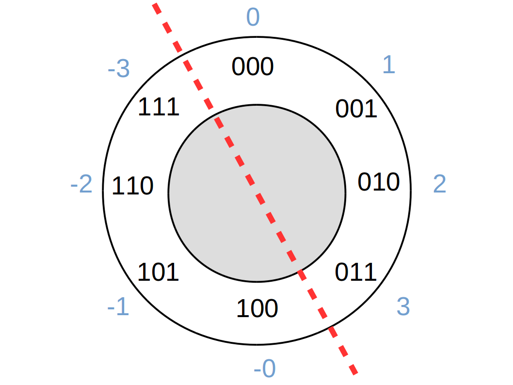
Taking our one’s complement clock face, our biggest headache is the double-zero. Logically we want the -0 to be -1, -1 to be -2, and so on. This inspires the use of two’s complement, which is formed by flipping all of the bits and adding 1. We retain the nice property that the MSB indicates the sign. In addition we find that the binary number 111 represents minus one (since the MSB tells us its a negative number and flipping all the bits and adding one gives 001). Putting this on our clock face:

This is very good news: addition always moves clockwise, subtraction anti-clockwise. There is no double-zero and only one discontinuity. In fact the circuitry that would act on this number is the same as the circuitry for unsigned integers. For example:
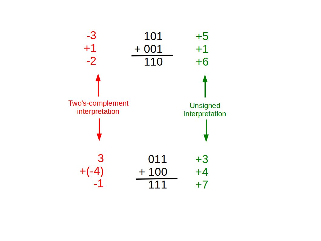
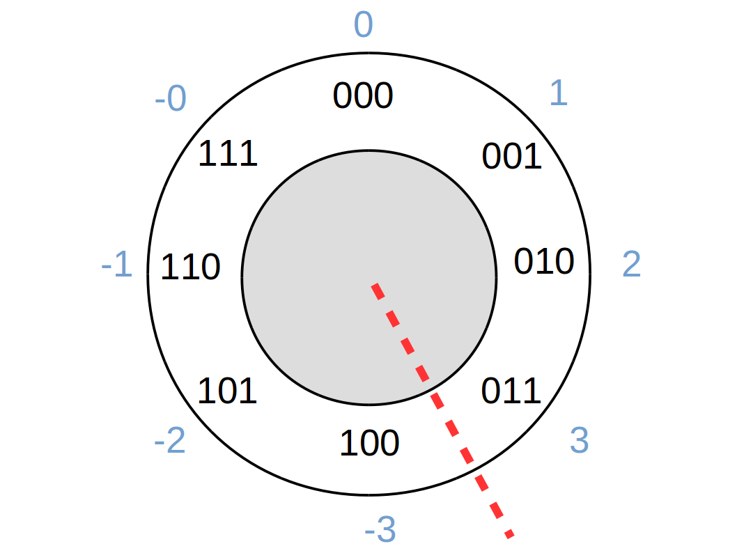
Although actually there’s a subtlety. The one discontinuity isn’t quite in the same place, meaning the overflow problem occurs at a different point. We can see this if we try something that crosses the unsigned discontinuity but not the signed one:
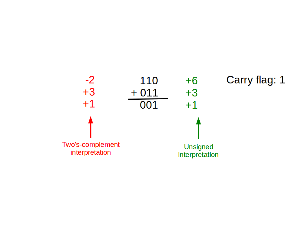
The unsigned version failed, but at least the carry bit was set so we know it failed. However, the signed version worked perfectly, despite the carry flag being 1. In fact, the carry flag is useless for signed arithmetic. We have to add a new flag, the overflow flag, to signify problems with signed arithmetic. This flag is set whenever the input numbers have the same sign (i.e. same MSB) but the answer has a different sign. In the example above, this isn’t the case, the overflow flag is zero and we know it worked OK. Here’s an example where we cross the two’s complement discontinuity:
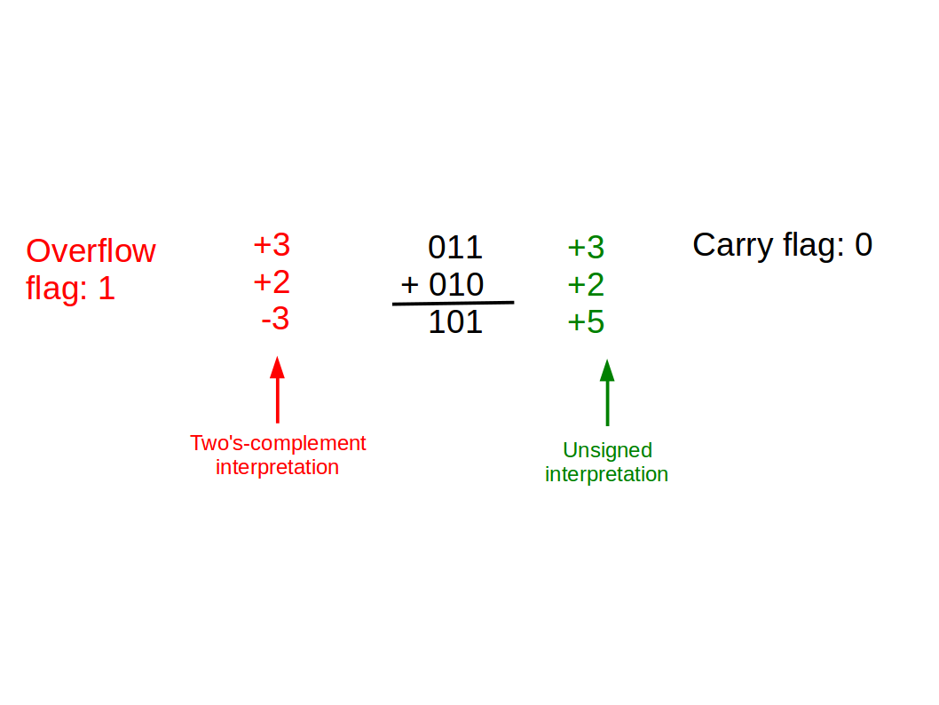
So, we use the same circuitry but we have one extra flag to watch for overflows. To recap: the carry flag is used to check the result if you are using unsigned inputs; the overflow flag is used to check the result if you are using signed inputs.
By using two’s complement we get:
- an efficient representation (no wasted or duplicated labels);
- the ability to use the same electronics for signed or unsigned numbers.
This is a big saving: less silicon, simpler designs, cooler and smaller chips. Consequently two’s complement is the almost-universal choice for representing signed integers in computers.
Fractional Numbers
You’re familiar with the notion of decimal points, which simply extends the idea of a decimal integer to include a fractional part by allowing negative powers of the base (10):
\[123.456 = 1\times10^2 + 2\times10^1 + 3\times10^0 + 4\times10^{-1} + 5\times10^{-2} + 6\times10^{-3}\]
The idea extends directly to binary (“binary point”):
\[101.101_2 = 1\times2^2 + 0\times2^1 + 1\times2^0 + 1\times2^{-1} + 0\times2^{-2} + 1\times2^{-3} = 5.625_{10}\]
As with integers, finite memory slots get in the way on computers. There are two main representations: fixed-point and floating-point. You’ll study these in detail in the coming year, but for now all you need to understand is that fixed point assigns a fixed number of bits to the whole (integer) part and the remainder to the fractional part; contrastingly floating point representation allows the point to float and is therefore more flexible but more complex to implement in computer hardware.
Conclusions
Binary is at the heart of a lot of computer science so it’s vital you have a thorough understanding of it and all the related things presented here. If you didn’t feel at ease with anything in this primer, it would be wise to spend time looking at it again before you arrive in Cambridge.