 (File | Project | Set Project to current file),
or choose File | Project | Name... and select the top-level design file.
The MAX chip (the buffer between the ARM and the FLEX) has detected that the chips were trying to drive a line in opposite directions. Separate the boards by turning the nearest DIP switch to the front of the box up.
You need to tell MAX plus where the top-level module of your project is, and where all of the
other files that go with it are kept. Open the top-level design file, and click on
 (File | Project | Set Project to current file),
or choose File | Project | Name... and select the top-level design file.
Are you sure you have the right project loaded? - see (2.1.1)
Check the .acf file - see (2.1.6). If the pin assignments aren't there, you probably had the wrong project loaded when you made the assignments. See if you can track them down, otherwise you'll have to make them again.
From the Assign | Device... dialogue box (oddly). You probably want to choose an EPF10K20RC240-4, for which you'll have to turn off Show only fastest speed grades, and set the Device family to FLEX10K.
For the sake of completeness, the MAX chip is an EPM7128SLC84-7.
From the Assign | Pin/Location/Chip... dialogue box. You need to assign any pins on your chip which perform a particular function. Note that for buses, you have to do each net individually. You enter the name of the port on your top-level module in the Node Name icon, and then the pin number in the Pin icon; then click on Add to add it to the existing assignments in the bottom icon.
You can select from the bottom icon to delete or change the assignments of a node (don't forget to click Change if you need to before closing the dialogue box).
Note that if you try to change the name of the net assigned to a pin, you'll end up with two nets assigned to the same pin, so you'll need to delete one.
Alternatively, you can forget about that and edit the .acf file by hand - see (2.1.6).
You haven't assigned a device. Click on Assign device... and see (2.1.3).
It's the file where all of the configuration for the current project is saved; this includes pin and device assignments, compilation options, and lots of other things.
For a large number of pin assignments, it's much easier to edit this file by hand rather than use the dialogue box interface. The first section, entitled CHIP <name> is the one which contains the assignments - there's a line for each pin, as well as one for the device assignment. It's probably easiest to make an assignment in the dialogue box first, or copy from another .acf so that you can see the right format.
Most likely, it means the programmer's looking for a file which hasn't been built yet. Close the Programmer window until you're ready to use it.
Again, the programmer's got confused. Open the JTAG | Multi-Device JTAG chain setup dialogue box, click on the first entry in the list of programming files, then click Change, and then OK.
It's a bug in Altera's software. You might find that enabling Processing | Total recompile, or restarting MAX+plus solves the problem.
Another trick, if the missing module is a separate file, is to switch project to that file and try to compile it. Once it compiles successfully (apart from messages about auto-selecting device types), try compiling the original file.
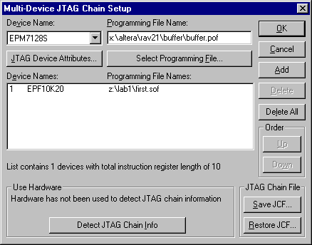
Well, pretty much what it says, actually. Check that the board has power (the Altera and ARM boards both have power LEDs), that the jumpers on the Altera board are set correctly, and that the information in the JTAG | Multi-Device JTAG chain setup dialogue box matches it.
To program the FLEX, you want the jumpers to be, starting from the back, to the left, left, right and right. In the dialogue box, you only want one entry in the Programming File Names list. It should look like this - what's important is the stuff in the big box in the middle, not the ones at the top.

Clicking on Detect JTAG chain info may give you a clue as to what's going wrong.
In the Waveform Editor, select File | End Time..., then change the end time in the Simulator window.
You can only set the clock to multiples of the grid spacing. In the Waveform editor, either turn off the grid altogether, with Options | Snap to Grid, or change its spacing, with Options | Grid Spacing....
The editor thinks you're dragging the mouse. Be certain to keep the mouse still when you click.