HOME
UP
PREV
NEXT (Basic Bus: One initiator (II).)
Architecture: Bus and Device Structure
In this section we examine the basic anatomy of a SoC.
Transmitting data consumes energy and causes delay. Basic physical parameters:
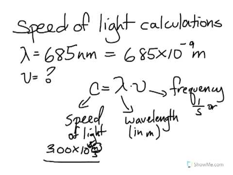
-
Speed of light on silicon and on a PCB is 200 metres per microsecond.
-
A clock frequency of 2 GHz has a wavelength of 2E8/2E9 = 10 cm.
-
Within a synchronous digital clock domain we require connections to be less
than (say) 1/10th of a wavelength.
-
Conductor series resistance further slows signal propagation and is dominant source of delay.
- So need to register a signal
in several D-types if it passes from one corner of an 8mm chip to the other!
-
Can have several thousand wires per millimetre per layer: fat busses (128 bits or wider) are easily possible.
-
Significant DRAM is several centimeters away from the SoC and also has significant internal delay.
Need to use protocols that are tolerant to registers (4P H/S degrades with reciprocal of delay).
(Die stacking and recent DRAM-on-SoC approaches reduce wire length to a few mm for up to 500 MB of DRAM.)
But first let's revist the simple hwen/rwen system used in the `socparts' section.