MultiMedia Logic
MultiMedia Logic
This note introduces the MMLogic MultiMedia logic design system from Softronics Inc.
Getting going
Starting the program
MultiMedia Logic is available on the University PWF systems. You can also obtain your own copy free of charge from http://www.softronix.com/.
- Using the mouse, click on the Start icon in the bottom left-hand corner of the desktop.
- Click on the second line of text on the left saying PWF Programs; a new window containing several icons will open.
- The window may be too small for you to see all its contents, in which case drag the bottom right hand corner outwards to reveal them. You do this by pointing at the diagonal stripes with the mouse, push the left button and hold it while moving the mouse down and to the right, releasing the button when the window is big enough.
- Double click the left mouse button (that is, press it twice in rapid succession) on the Teaching Packages icon in this window and another window will appear.
- Double click on the Computer Laboratory icon and yet another window will appear.
- Finally, double click on the Multi Media Logic icon to start the program.
- A window with a message about MSW may appear; if it does, just click the OK button and it will go away.
- A window with a tip about using the program may appear; if it does, just click the Close button and it will go away.
- Click on the Full screen button of the Multimedia Logic window (a rectangle on the right in the banner at the top of the window).
- Inside the Multimedia Logic
window there is another window called Logic 1. Click on
its Full screen button.
The screen should now look like this: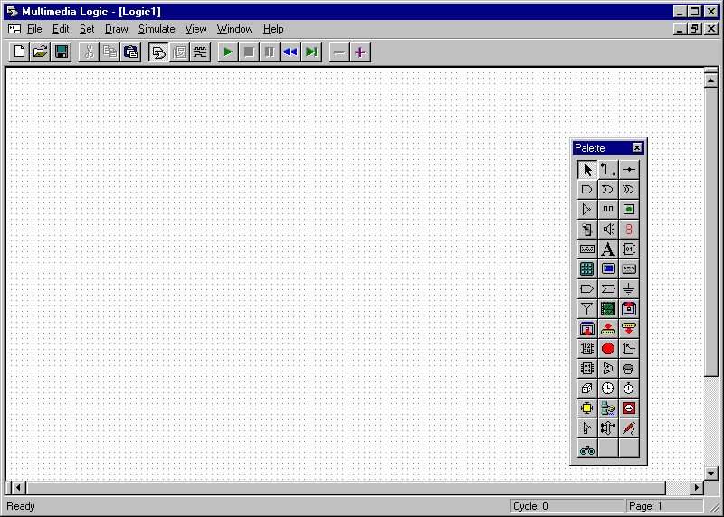
- If the Palette is not visible, click on the first button in the third group of three icons at the top of the window.
- Use the mouse to move the palette to the right-hand side of the window by pointing at its title and dragging it across (push the left-hand mouse button and hold it down while moving the mouse).
Drawing a circuit
- Click on the symbol for an AND gate, which is the first icon in the second row of the palette; the cursor will change to a plus sign (+).
- Move the mouse to the middle of the window and click the left-hand button; a large AND gate will appear. Be careful not to click the button more than once or several gates will appear.
- Click on the arrow symbol, which is the first icon in the top row of the palette.
- Point at the AND gate and drag it round the screen.
- Press the DELETE key on the keyboard and the AND gate will disappear.
- Move the mouse to the list of menus at the top of the window and click on Edit; a menu will drop down.
- Click on the word Undo and the AND gate will reappear.
Remember these tricks in case you make any mistakes. If you put part of the circuit in the wrong place, you can select it with the arrow and then drag it to the right place. If you accidentally draw something that is not wanted, you can select it and delete it. If you make any mistake, you can always undo it.
A surrounding box highlights the currently selected part of the circuit. You can click anywhere on the background to deselect everything (which may help you see details in the circuit).
Adding more components
- Click on the symbol for a switch, which is the first icon in the fourth row of the palette.
- Move the mouse to the left-hand side of the window and click the left-hand button twice to make two copies of the switch, one just above the level of the AND gate and one just below.
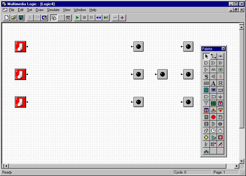
- Click on the symbol for a light-emitting diode (LED), which is the third icon in the third row of the palette.
- Move the mouse to the
right-hand side of the window and click the left-hand button twice to
make copies of the LED, roughly level with the two switches.
The screen should now look like this:
- Notice the little black dots on the stalks to the left and right of the components; these are connection points. Each switch has one connection point on its right-hand side, each LED has one on its left-hand side and the AND gate has two on its left-hand-side and one on its right-hand side.
Wiring the components together
- Click on the symbol for a wire, which is the second icon in the top row of the palette; the cursor will change shape to a plus sign.
- Point carefully at the connection point on the right-hand side of the top, left switch.
- Press the left-hand button and drag a wire across to the upper connection point on the left-hand side of the AND gate, then release the button.
- If you miss the connection point on the switch, a little window will pop up saying Error Nothing to connect to. Just click on OK and it will go away so you can try again.
- If you miss the connection point on the AND gate, the wire will disappear. Just try to draw it again.
- Join the lower switch to the lower connection point on the left-hand side of the AND gate similarly.
- Join the connection point on the right-hand side of the AND gate to the upper LED similarly.
- Now join the connection
point on the right-hand side of the AND
gate to the
lower LED. Notice that you can have two wires connected to a
single connection point.
The screen should now look like this: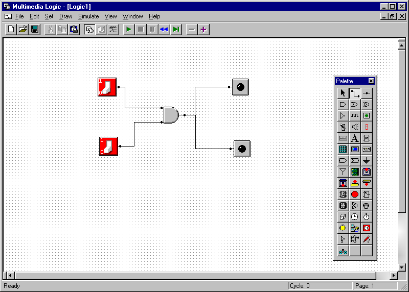
- If there are any problems, just correct them by deleting and replacing components or wires. When selecting a wire, you have to point at its end; if you point to the right-hand connection point on the AND gate, you will select both of the wires.
- Try dragging the components and notice how the wires stay connected.
Testing a circuit
- Click on the green triangle which is the first icon in the fourth group at the top of the screen.
- A window may pop up inviting you to save the logic. Just click on the Cancel button and it will go away.
- Click on the two switches to turn them on and observe that the two LEDs come on. (They are American switches, so up is on and down is off.)
- Turn them on and off a few
times to convince yourself that the AND
gate is
working correctly. Write the results in a table like this:
Upper switch Lower switch LEDs Off Off Off On On Off On On - Compare the results with the carry output of a binary adder.
- Click on the red square next to the green triangle in the fourth group of icons at the top of the window and the simulator will stop. The palette should re-appear.
The palette will disappear and the box labelled Cycle at the bottom right-hand side of the window will start counting up.
Changing a circuit
- Move the mouse to
the AND gate and click the
right-hand
button; a menu will pop up. Click on
Properties… and a
window labelled AND
Gate Properties will pop up:
- Click in the box at the bottom left-hand side of the window so that a tick appears just before the text Invert Output (NAND).
- Click OK.
- Notice how the AND gate now has a little circle on its right-hand side, showing that its output has been inverted; it is now a NAND gate. You may need to deselect the gate by clicking on the background of the screen before this becomes clear.
- Simulate the new circuit and
see the difference in its behaviour. Write the results in a table like
this:
Upper switch Lower switch LEDs Off Off Off On On Off On On - Click on the red square next to the green triangle in the fourth group of icons at the top of the window to stop the simulator when you have finished.
Wiring faults
- Sometimes an LED will appear half lit, rather than fully off or on. This means that the system has been unable to work out whether the value on the wire driving it is a 0 or a 1. For example, this happens when there is no wire driving it.
- This should not happen in the circuits described here. If you see a half lit LED, it probably means that you have made a mistake with the wiring. Stop the simulator, and use the arrow to move components around. The wires should stay attached. If they don't, you will need to delete the wires and redraw them more carefully.
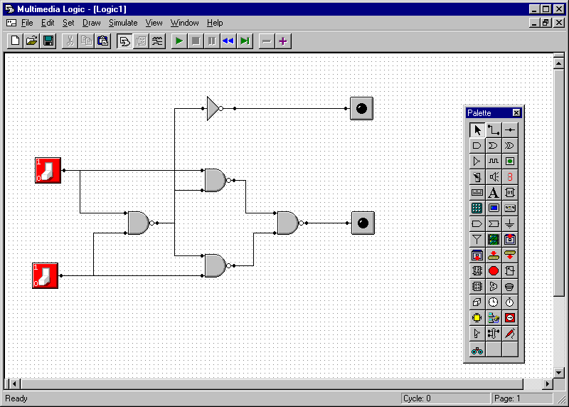
Making an adder
- Start a New Project by clicking on the first icon (and empty sheet of paper) in the first group at the left-hand side of the top of the screen.
- Draw the following circuit:
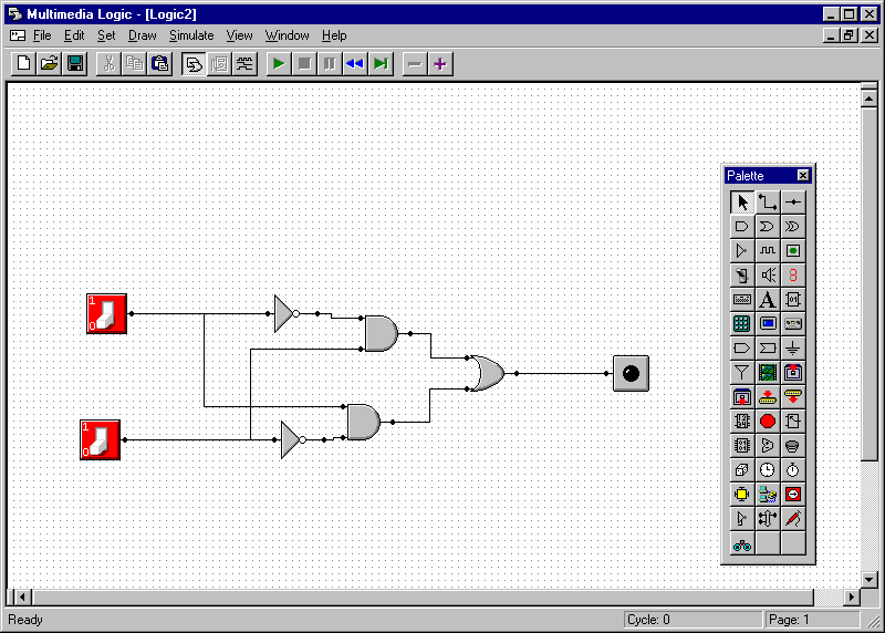
- Note that some new components are used. There are two invertors (the first icon on the third line of the palette) and an OR gate (the second icon on the second line of the palette). The two switches each have to wires coming from them, which may be drawn overlapping eachother.
- Turn the switches on and off a few times to investigate the circuit's behaviour.
- Write the results in a table like this:
Upper switch Lower switch LEDs Off Off Off On On Off On On - Compare the results with the sum output of a binary adder.
- This circuit is called an Exclusive OR or XOR. It is so useful that there is even a special symbol for it; it looks like an OR gate with an extra curving line on the left-hand side.
- Delete the two invertors, the two AND gates and the OR gate from the circuit.
- Replace them with a single XOR gate (the third icon on the second row of the palette).
- Check that the circuit still works.
Adding with carry
- Start a new project and draw
the following circuit:
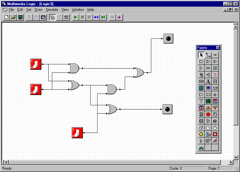
- Turn the switches on and off a few times to investigate the
circuit's behaviour. Fill in the results in a table like this:
Left upper switch Left lower switch Bottom switch Upper LED Lower LED Off Off Off Off Off On Off On Off Off On On On Off Off On Off On On On Off On On On - Compare the results with the table for a full adder.
Adding two digits
- Copy the circuit and replace
the upper LED of the bottom circuit and the bottom switch of the top
circuit by wires. The Node icon (at the
right-hand side of the top row of the palette) can be used to make
guide points for the wires that have to run backwards:
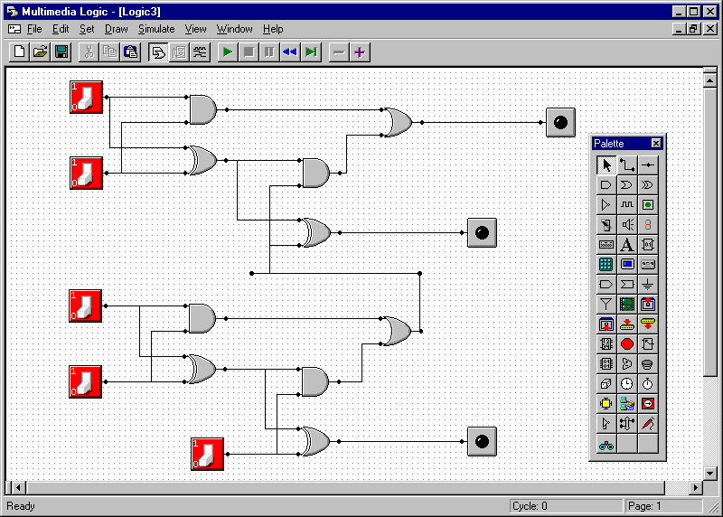
- Working from top to bottom, label the switches down the left-hand side A2, B2, A1, B1 and C, and label the lights down the right-hand side S4, S2 and S1.
- This circuit should do the
following binary calculation:
A2 A1 B2 B1 + C S4 S2 S1 - The two columns in the addition are built as two strips across the circuit. The bottom strip adds A1, B1 and C to give S1 and a possible carry to the top strip, which adds it to A2 and B2 to give S2 and a possible carry to S4.
- Test it by filling in some
values into a table like this:
A2 A1 A B2 B1 B C S4 S2 S1 S - In each row, work out the decimal values of A for the binary values on the two wires A2 and A1, the decimal value of B on B2 and B1, and the decimal value of S on S4, S2 and S1.
- What does the circuit do?
- Can you see how to extend this to more than two digits?
Other circuits
If there is time, you might like to design some circuits of your
own. Here are some ideas.
- In practice, it is much
easier to make NAND gates than
AND gates. Check that the
following circuit
calculates the sum and carry of its inputs:
- Consider an electronic
die.
- Given a binary value between 0 and 7 input on three
switches, drive seven LEDs to show the standard patterns for the
numbers 1 to 6 (and something sensible for 0 and 7). Here is
an outline of the problem:
- If you think about it, the lights come on in particular
patterns. The one at the top left always comes on at the same
time as the one at the bottom right. Call the three switches
S4, S2 and S1 (corresponding to their binary values) and the lights A,
B, C and D with A, B and C down the left hand side and D in the middle,
so C, B and A are repeated down the right hand side. So the
labels look like:
S4 A C S2 B D B S1 C A - The table for inputs and output is as follows:
S4 S2 S1 Value A B C D 0 0 0 0 0 0 0 0 0 0 1 1 0 0 0 1 0 1 0 2 1 0 0 0 0 1 1 3 1 0 0 1 1 0 0 4 1 0 1 0 1 0 1 5 1 0 1 1 1 1 0 6 1 1 1 0 1 1 1 7 1 1 1 1 - Work out the circuit for calculating each of the four output signals A, B, C and D from the three input signals S1, S2 and S4. D and C are pretty easy. B and A need a little more thought.
- Given a binary value between 0 and 7 input on three
switches, drive seven LEDs to show the standard patterns for the
numbers 1 to 6 (and something sensible for 0 and 7). Here is
an outline of the problem:
- Consider how you might multiply two (unsigned) binary numbers. Start by working out how to multiply two single binary digits. (This is fairly easy!) Then work out how to multiply a two-digit binary number by 2 (or by 4 or by 8). Finally, write out the long multiplication for a pair of two-digit binary numbers. You will need some adders to complete the sum.
- All the circuits so far just
calculate outputs directly from their inputs. How might we
make a store?
- The following circuit is called an RS-latch:
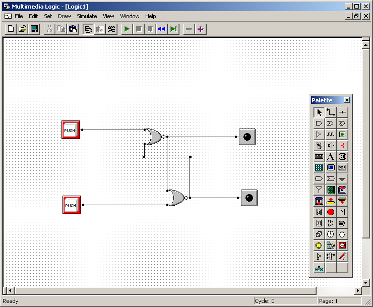
- You will need to be a bit careful when drawing this.
- Change the properties of the switches so that they are momentary, that is, they work like push buttons.
- Change the properties of the OR gates to invert their outputs, so they become NOR gates. Finally, you will have to use the Node icon to make guide points for the wires that have to run backwards.
- The top light shows the value stored in the latch, and the bottom light shows the opposite value. Pushing the top button clears the value, so the top light should go out. Pushing the bottom button sets the value, so the top light should come on.
- When the circuit starts up, the stored value is unknown, so both LEDs are shown as half on.
- The following circuit is called an RS-latch: