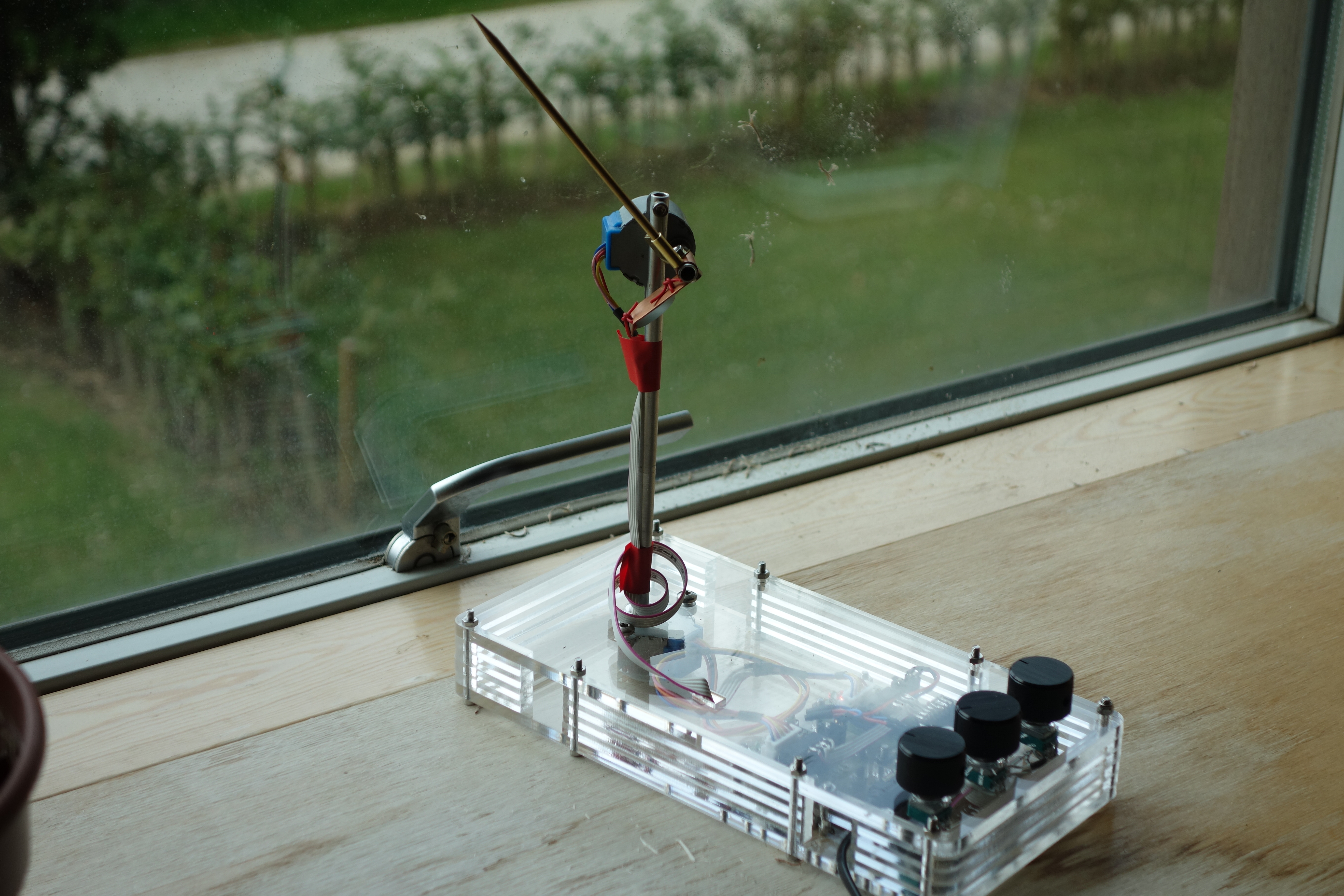
as a live electric orrery, to continuously point to any one of the major solar system objects (sun, moon,
or planets); or
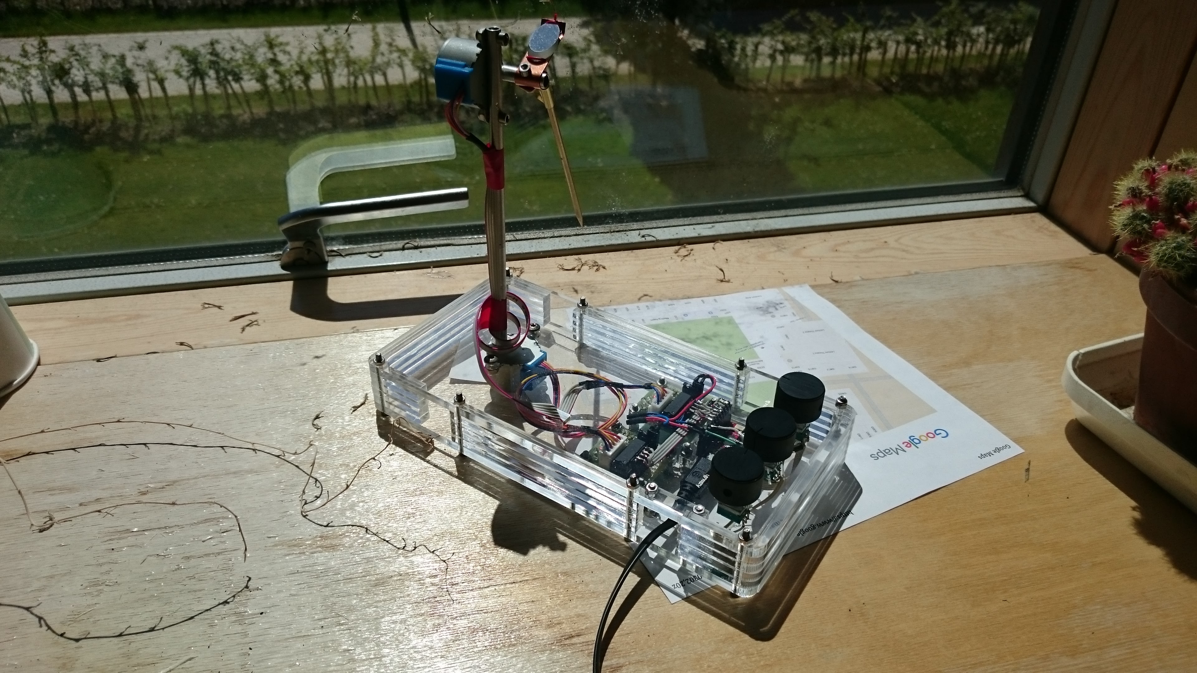
as a mirrored-pinhole heliostat, to continuously reflect an image of the
sun in a constant (but adjustable) direction. The image is
approximately 1cm diameter for each meter of distance between the
device and whatever the image is reflected onto.
Use
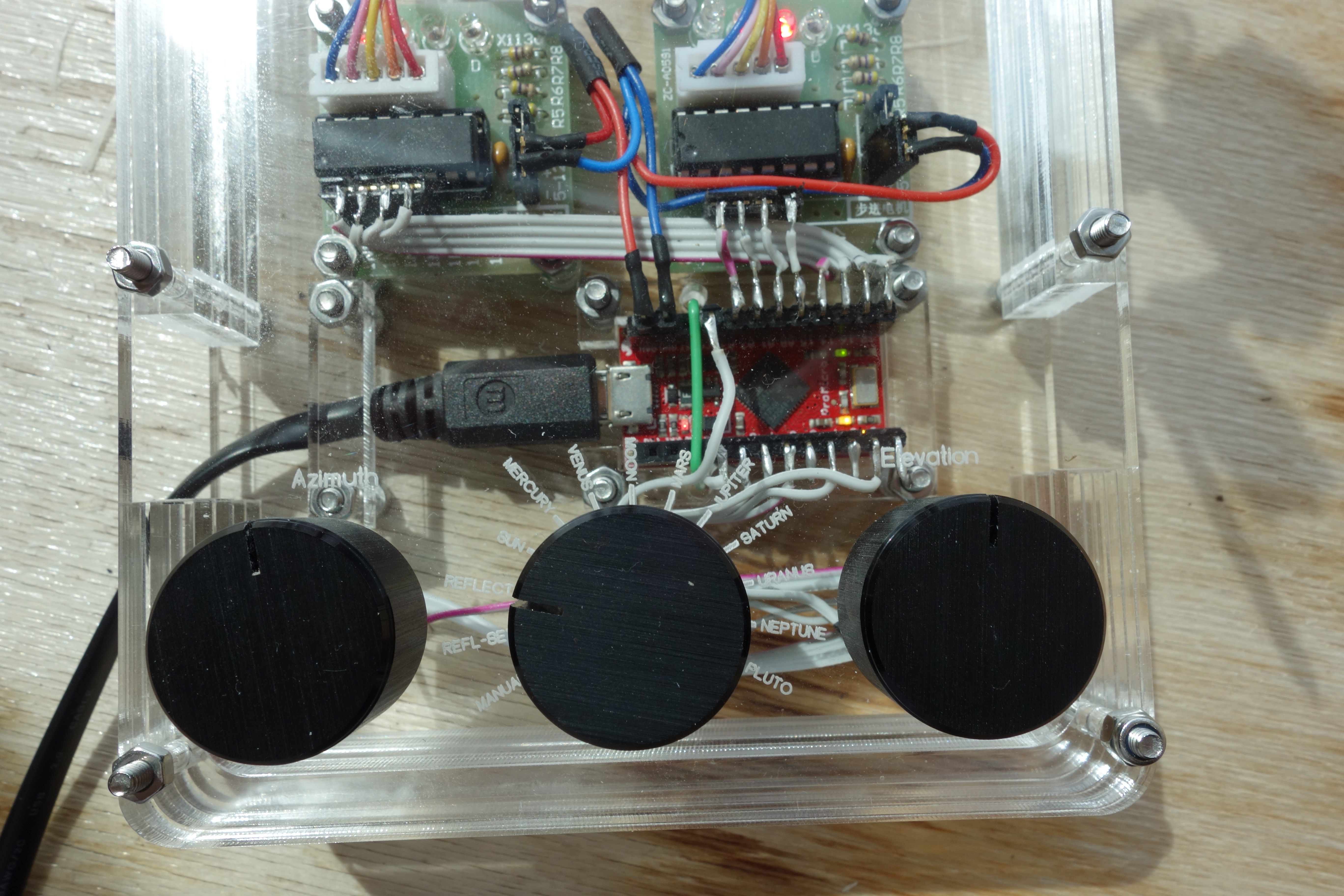
Dial the control knob to the desired mode:
for SUN, MERCURY, VENUS, MOON, MARS, JUPITER, SATURN, URANUS, NEPTUNE, PLUTO,
the pointer will point at that object.
in MANUAL (or REFL-SET) mode, the Azimuth and Elevation knobs can be
used to set the pointer direction manually
(Azimuth is the angle clockwise from North; Elevation is the
angle up from horizontal).
in REFLECT mode, the mirror will be oriented to reflect
an image of the sun in the desired direction - initially the
manual-mode pointer direction, and adjustable with the Azimuth and
Elevation knobs.
Accuracy
The calculated directions should be accurate, but the cheap stepper
motors used have a lot of backlash (approximately 10 sun angular
diameters), the pointer and mirror are not exactly parallel, and the
initial calibration is usually rough. Pointer directions should be
good to within maybe 10 degrees, and the sun reflection is kept stable
within something like 10 sun angular diameters. The steppers have
approximately 2048 steps / revolution, so one step is roughly 1/3 of
the sun's angular diameter.
Reflection
The mirror gives a good image of clouds moving across the sun, but the
resolution is probably not good enough to see sunspots (at least at
the viewing
distances we've tried, up to 30m or so). If projecting into a
darkened room, one could use a smaller aperture by blanking off some
of the mirror, as in Hugh Hunt's
Venus Transit setup.
Calibration and setup
The client code, pointer_aa, should build just
with make. The device should be connected to the USB
before running the client code.
Control-C will reset the device to its initial position and exit.
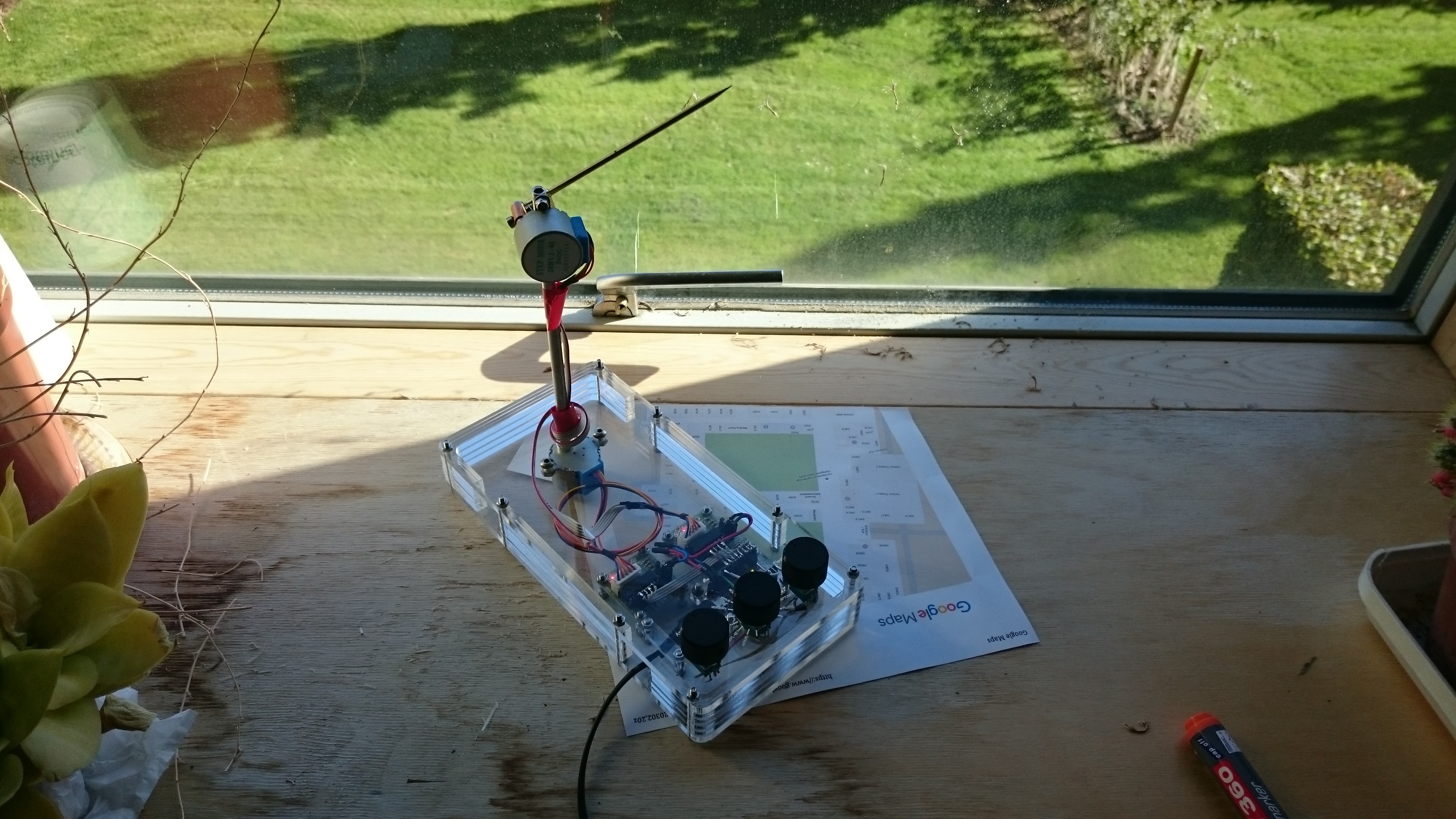
Before power-on, the pointer should be pointing horizontally due North, with at least half a turn of slack in both directions in
the ribbon cable. If not, power up in Manual mode, start up the
client code, use the knobs to adjust the pointer, unplug, and start
again. Printing out a Google map image that shows the orientation of
the building gives an easy way to orient with respect to North.
The latitude and longitude of the observer need to be set
in aa.ini.
The device name of the USB serial link differs between operating
systems and can vary. On an Ubuntu Linux machine it's usually ttyACMx
for some number x, and the client code tries several options. On
other machines this may need to be edited.
To set the right permissions, on Linux one can
sudo chmod 666 /dev/ttyACMx, or more permanently
add the user to the dialout group with sudo usermod -a -G dialout USERNAME
(and log out and in).
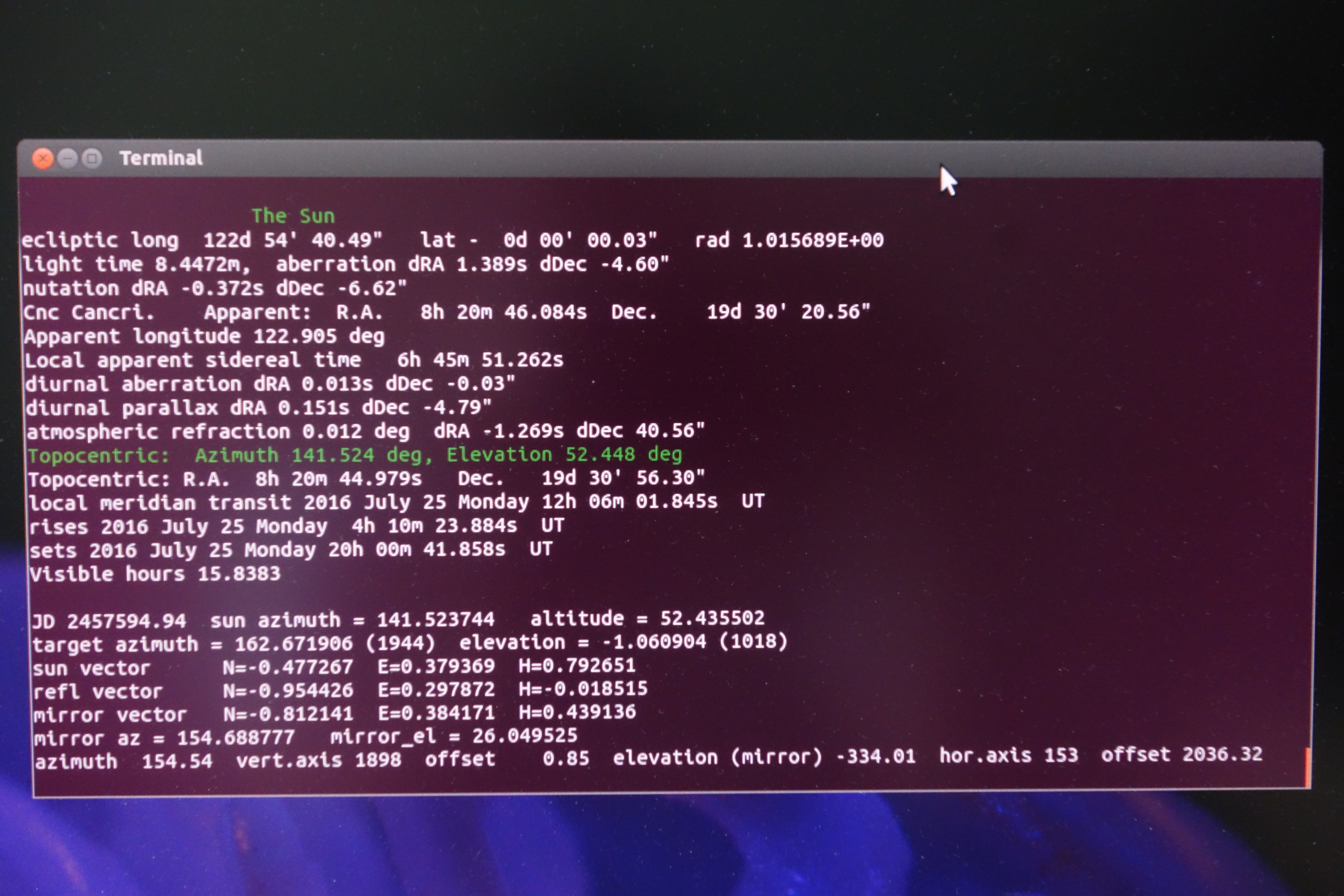
Design
The device uses two cheap geared stepper motors connected to an Arduino pro
micro, controlled over a USB serial link by C client code running on a
PC. The client code does most of the work, using code from Moshier's
aa-56.zip to compute topocentric
coordinates of astronomical objects.
The Arduino code uses the AccelStepper library to control the stepper
motors; it also reads the knob values and discretises the control
knob.
Limitations
This hardware is cheap, easy to build, and easy to source, but it has
several downsides:
there is no position sensing at all, of the latitude and longitude of
the device, of its orientation, or of the stepper motor positions: it
relies entirely on the user setting up the initial orientation, and on
open-loop control, counting steps, thereafter. If one only wanted a mirrored pinhole
heliostat, that could be done with closed-loop control with a
webcam.
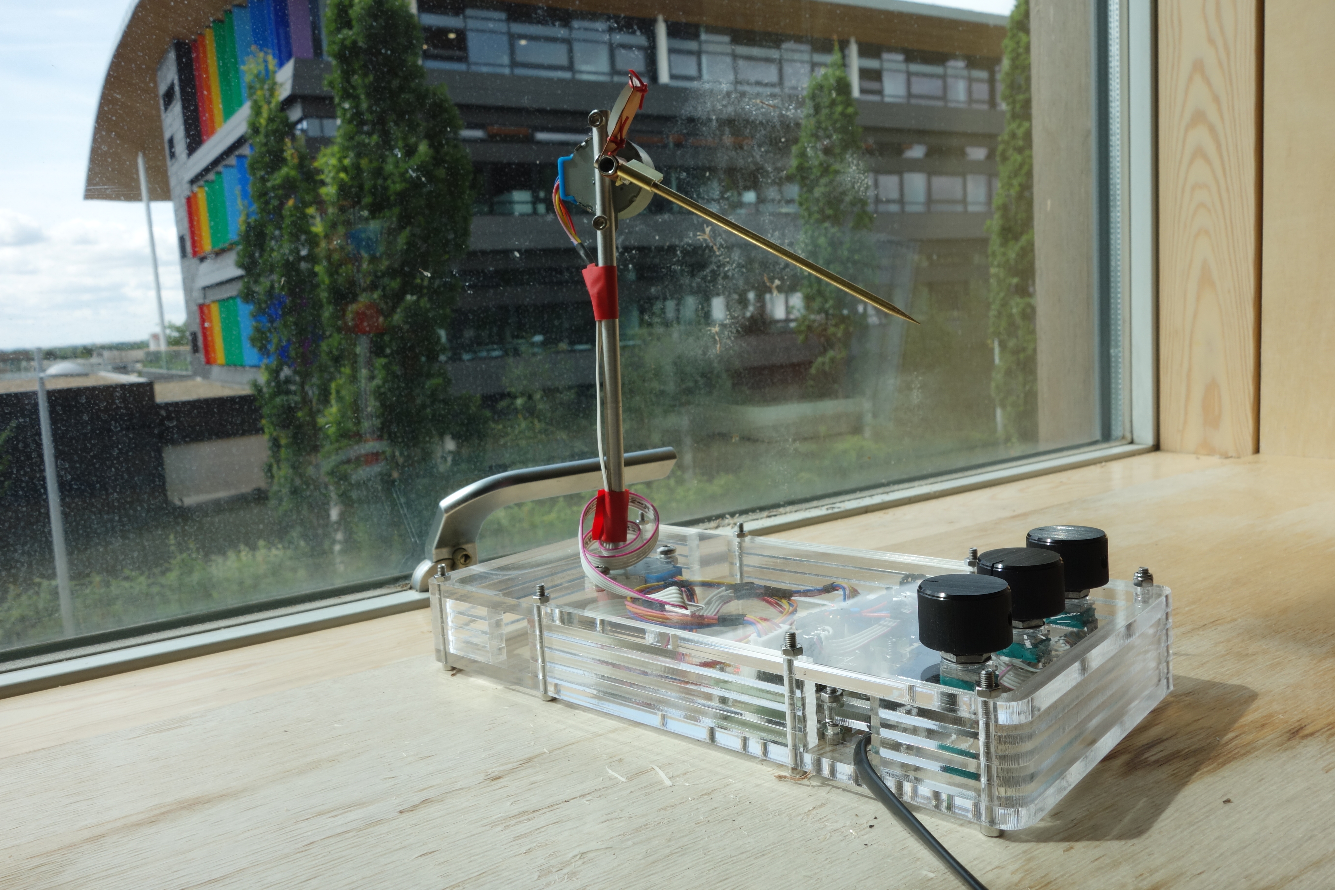
the elevation stepper is wired directly (rather than via a
slip-ring); it relies on having enough slack for at least half a
rotation in each direction.
the pointer and mirror axes are only roughly parallel.
the steppers have considerable backlash, as mentioned above.
it relies on the stepper bearings to keep the axes perpendicular
to the case and to the vertical axis; both have considerable angular play.
it uses a PC to run the client code - that could presumably
easily be ported to a Raspberry Pi or other more substantial
microcontroller, so long as a real-time clock is available.
the astronomy code can also calculate positions of some stars,
but the hardware user interface doesn't support that
there's no support for pointing to other objects, e.g. the ISS
Possible minor improvements
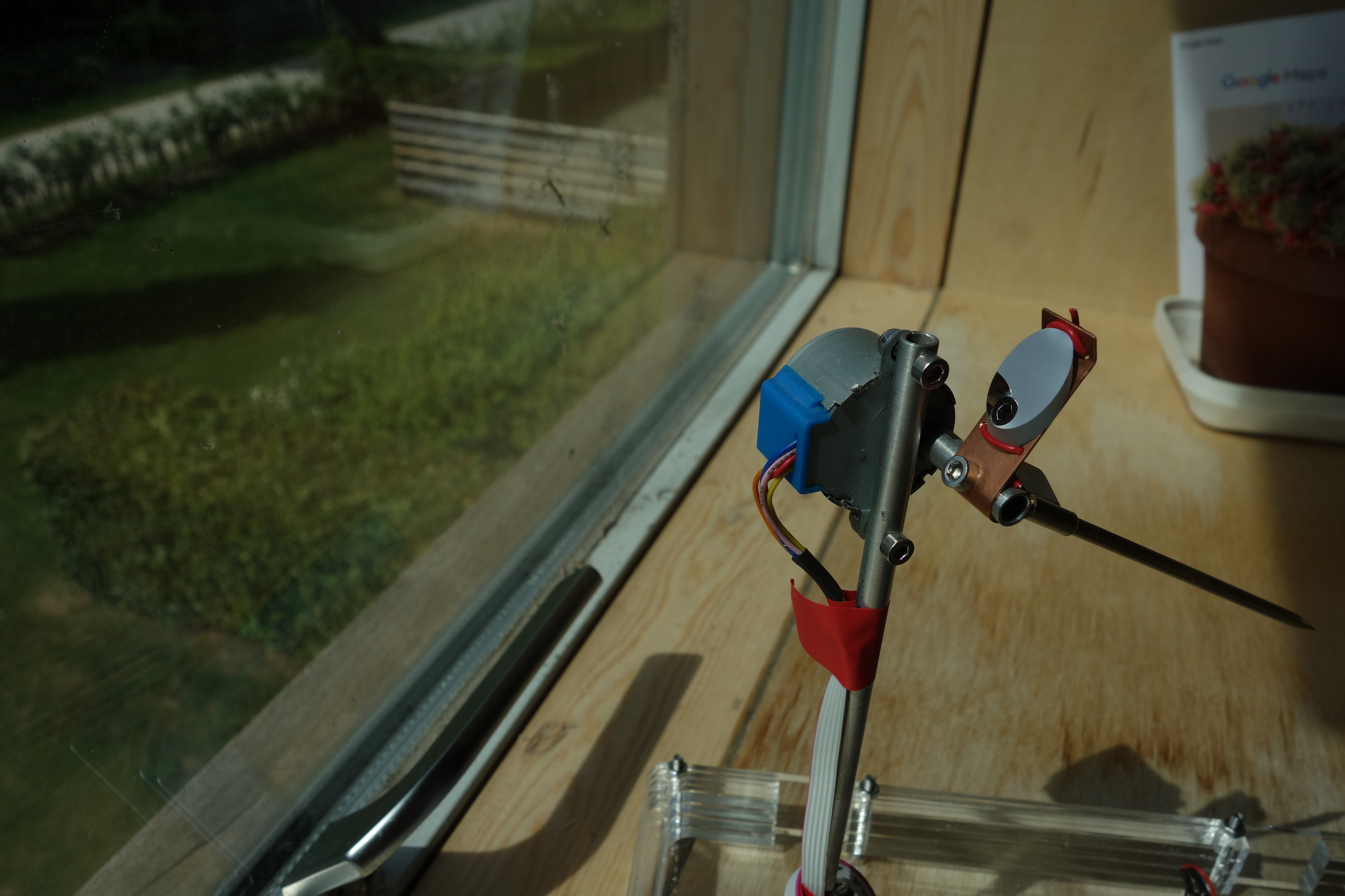
rotate the upper stepper mount 90 degrees to put its axis at the
top, to reduce the occasions on which the stepper partially shades
the mirror
add a disc concentric with the vertical axis, near the case, to
constrain the ribbon cable into a tidier spiral
run the cable to the upper stepper inside the tube
space the control knobs further apart, to let the font size be increased
Mirror: Elliptical Mirror, 12.7mm Mirror Axis, 3mm thk, Protected Aluminium
(Visible Applications),
from Knight Optical (£15
+ shipping) (This is an optically flat front-surface mirror,
avoiding multiple reflections. A circular mirror would also be fine, with a slightly
different mounting arrangement, and a conventional back-surface
mirror would likely also be ok. The size is a tradeoff between
brightness and resolution.)
Pointer: 3mm brass rod, turned
Pointer and mirror mounting: aluminium tube, drilled to push-fit onto
steppers, and scraps of copper and brass sheet.
Knobs and potentiometers from RS: Alps Potentiometer RK097 Series with
a 6 mm Dia. Shaft 10kΩ ±20% 0.05W, Linear, Panel Mount (Through Hole),
Stock no.: 729-3482. RS Black 22mm Aluminium Potentiometer Knob with
a Black Indicator, 6.35mm Shaft Stock no.: 498-839.
Arduino: an Arduino Pro Micro 3.3v (any other
Arduino would probably do)
Hardware: M3x35 and M3/x16 ST/ST socket
cap screws from PTS-UK
vertical (azimuth) axis, arduino pin to stepper controller board pin:
15 1N1
14 1N2
16 1N3
10 1N4

horizontal (elevation) axis:
A3 21 1N1
A2 20 1N2
A1 19 1N3
A0 18 1N4

stepper controller power:
RAW   "+"     red
GND   "-"     blue

potentiometers:
GND     pot gnd
    2
    3
A6  4   Azimuth
    5
A7  6   Control
    7
A8  8   Elevation
    9

potentiometer ribbon cable, from red side:
  Azimuth   -> 4
  Control   -> 6
  GND       -> GND
  Elevation -> 8
  VCC       -> VCC
License
This description, the Arduino code (pointer.ino), the
client top-level code
(pointer_aa.c, pointer_aa.c, pointer_aa_interface.h)
and the case design
(box2.svg, box2-pathed.{svg,dxf,ecp}) are
(c) Peter Sewell, 2016; they are made available under the
Creative Commons Attribution-NonCommercial 4.0
International Public License (CC BY-NC 4.0)
(original
source). The astronomy code files (the remainder of the client
code) are by Stephen L. Moshier; they appear to have been placed in
the public domain (November 1987 and December 1998).

