⇡ Tutorial for the v0.4 lowRISC release
Hierarchical tag cache
Motivation
The tagged memory mechanism augments each data word in memory with a small piece of extra metadata, a tag. A separate area in high memory is dedicated to the tags, which is hidden to software. As a result, each memory access to the memory is converted into two separate accesses, one for the actual data word and another one for the tag. For a naive design, the speed/throughput overhead of supporting tagged memory is 100%! The overhead can be reduced to a small fraction of that through the use of an additional tag cache.
A small tag cache was used in our previous tagged-memory release. That tag cache was a conventional write-back set-associative cache. We had run the SPECInt 2006 benchmark suite using this tag cache. It was found that if the tag cache is large enough, most of the extra traffic accessing tags can be avoided. However, the size of the tag cache is significant compared with the size of L2$. We would like to further reduce the size of the tag cache while maintaining a low traffic overhead.
| I$ 8KiB (MPKI) |
D$ 16KiB (MPKI) |
L2 256KiB (MPKI) |
Mem traffic without tag (TPKI) |
Tag$ 16KiB (MPKI) |
Traffic Ratio |
Tag$ 32KiB (MPKI) |
Traffic Ratio |
Tag$ 64KiB (MPKI) |
Traffic Ratio |
||||
|---|---|---|---|---|---|---|---|---|---|---|---|---|---|
| perlbench | 20 | 5 | <1 | 2 | <1 | 1.289 | <1 | 1.089 | <1 | 1.025 | |||
| bzip2 | <1 | 14 | 10 | 16 | 10 | 1.941 | 7 | 1.688 | 3 | 1.281 | |||
| gcc | 15 | 11 | 4 | 6 | 2 | 1.497 | <1 | 1.240 | <1 | 1.072 | |||
| mcf | <1 | 168 | 104 | 136 | 67 | 1.651 | 40 | 1.409 | 11 | 1.128 | |||
| gobmk | 24 | 8 | 3 | 6 | 1 | 1.368 | <1 | 1.146 | <1 | 1.073 | |||
| sjeng | 11 | 5 | 1 | 3 | 1 | 1.673 | <1 | 1.482 | <1 | 1.383 | |||
| h264ref | 1 | 3 | 2 | 3 | <1 | 1.480 | <1 | 1.265 | <1 | 1.109 | |||
| omnetpp | 40 | 5 | <1 | <1 | <1 | 1.653 | <1 | 1.415 | <1 | 1.190 | |||
| astar | <1 | 21 | 5 | 9 | 4 | 1.750 | 2 | 1.471 | <1 | 1.173 | |||
| average | 12 | 27 | 14 | 20 | 10 | 1.589 | 6 | 1.356 | 2 | 1.159 |
General concept of a hierarchical tag cache
In this release, we observe that most of the memory is not tagged for most use cases. Therefore, we can implement optimisation based on an hierarchical tag cache to compress the unset tags cached in the tag cache. It is likely that most of the tags cached are unset in normal operation condition. By analogy with the cache lines of recently used data, tag cache lines contain recently used tags. A tag cache line is just a normal cache line in the tag cache; however, this cache line stores tags rather than data. To utilise this pattern, a hierarchical cache uses bit-maps to record the tag cache lines containing tags. When a whole tag cache line is unset, the bit-map is enough to fully represent the cache line; therefore, the actual unused line is no long needed to be cached (no need to access it from memory as well). As a result, a small tag cache is able to describe the tag state of a much larger region of memory, provided that memory has significant areas where no tags are set.
The logical view of the hierarchical tag cache is depicted below. It adopts a multi-tree structure where leaf nodes at tag table level hold the actual tags while the nodes in higher levels (tag map 0 and tag map 1) hold bitmaps identifying the used lower level nodes.
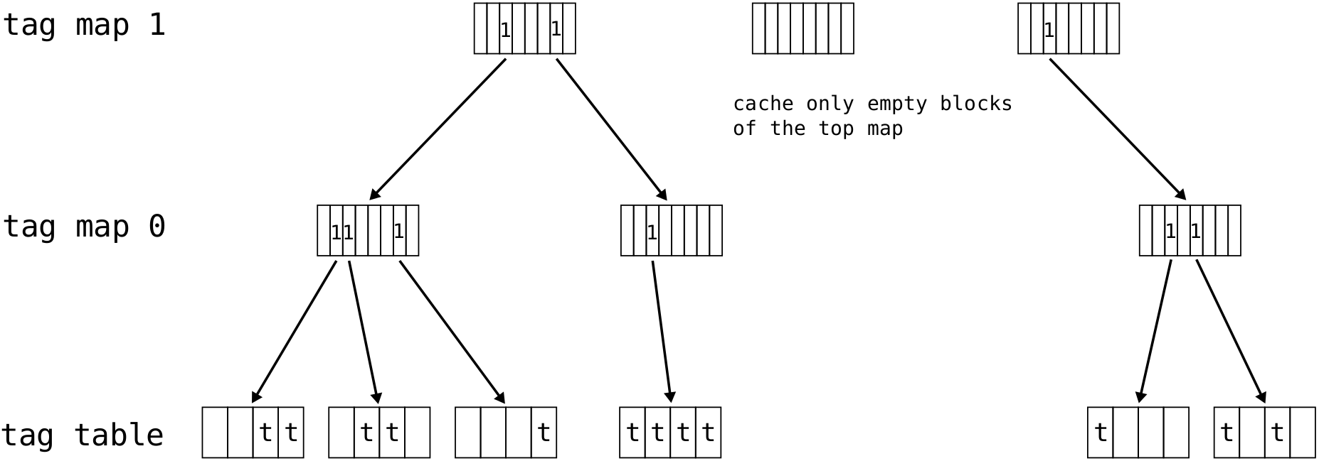
All levels of the hierarchical tag cache are backed by the memory; therefore, all nodes in the tree can be safely written back to memory when necessary. Fortunately, tag maps do not increase the actual memory requirement compared with using a plain tag cache. The spare space available in the reserved tag partition in memory is large enough to store the maps.
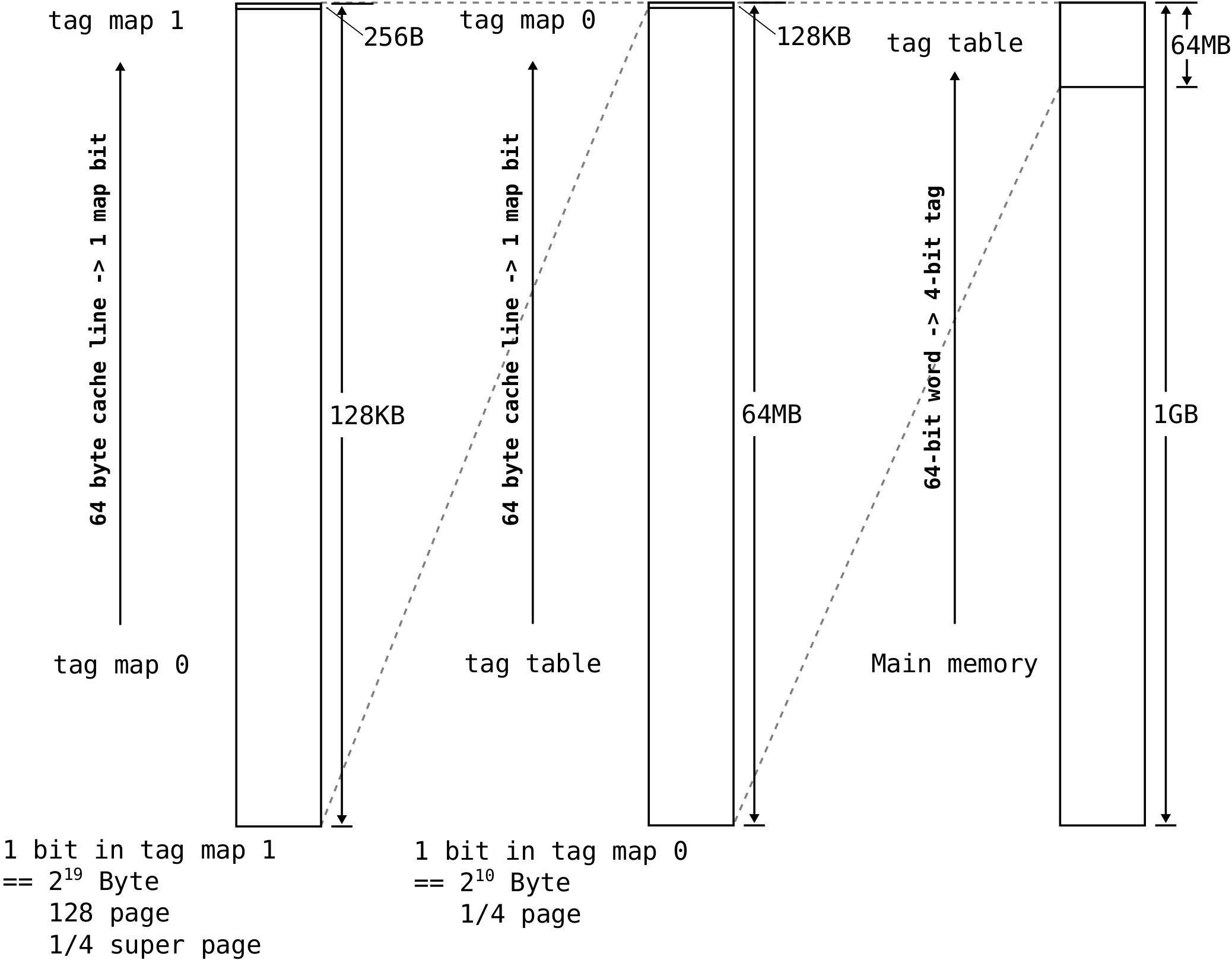
For a tagged memory that attaches \(N\) bits for each 64-bit word, \(\frac{N}{64}\) memory space is reserved for the tags. As a result, this reserved \(\frac{N}{64}\) memory space is not tagged and its associated tag space is never accessed, which is the upper \((\frac{N}{64})^2\) of the memory space. Each lower level node is mapped to 1-bit in a higher level node. Assuming a node is 64 bytes, the required memory for tag map 0 is \(\frac{N}{64 \cdot 64 \cdot 8}\). Since \((\frac{N}{64})^2 \ge \frac{N}{64 \cdot 64 \cdot 8}\), tag map 0 does not need extra memory space. Similarly it can be proved that tag map 1 is smaller than the spare space made available by tag map 0.\(\Box\)
The following graph shows the physical arrangement of data, tags and tag maps in a 1 GB memory. The tags of the 1 GB memory (nodes of the tag table) are located in the upper 64 MB of the address space. This area is then hidden and direct access from software is prohibited. The upper 128 KB of the tag table area is reserved for tag map 0, and the upper 256 bytes of the tag map 0 space is reserved for tag map 1. For normal SoC systems, two levels of tag maps are enough to reduce the top map to around 1KB. When the software makes no use of tags, a tag cache as small as 1KB is enough to eliminate all throughput overhead related to tagged memory.
Amongst other benefits, this hierarchical tag cache offers increased cache capacity when a large portion of memory words are not tagged.
The potential costs are:
- Complicated control logic to maintaining the consistency between tag table nodes and tag map nodes.
- Extra cache space to store tag map nodes in the tag cache, although in most workloads it is expected the more efficient caching of untagged memory regions will compensate for this cost many times over.
- Every node occupies a full cache line in the tag cache.
Full benchmarking and evaluation will come in a later release.
Hardware implementation
Instead of using three separate caches to store the tag table and the two tag maps, a unified cache is used. Nodes from all tree levels use the same size so they can be stored and searched in the same manner. This also allows dynamic space allocation between the table nodes and the map nodes. When most memory words are tagged, map nodes can be replaced to store table nodes; when most memory words are not tagged, the cache will primarily hold map nodes. The default block size is 64 bytes. Cache organisation is set-associative.
The internal structure of the hierarchical tag cache is depicted below:
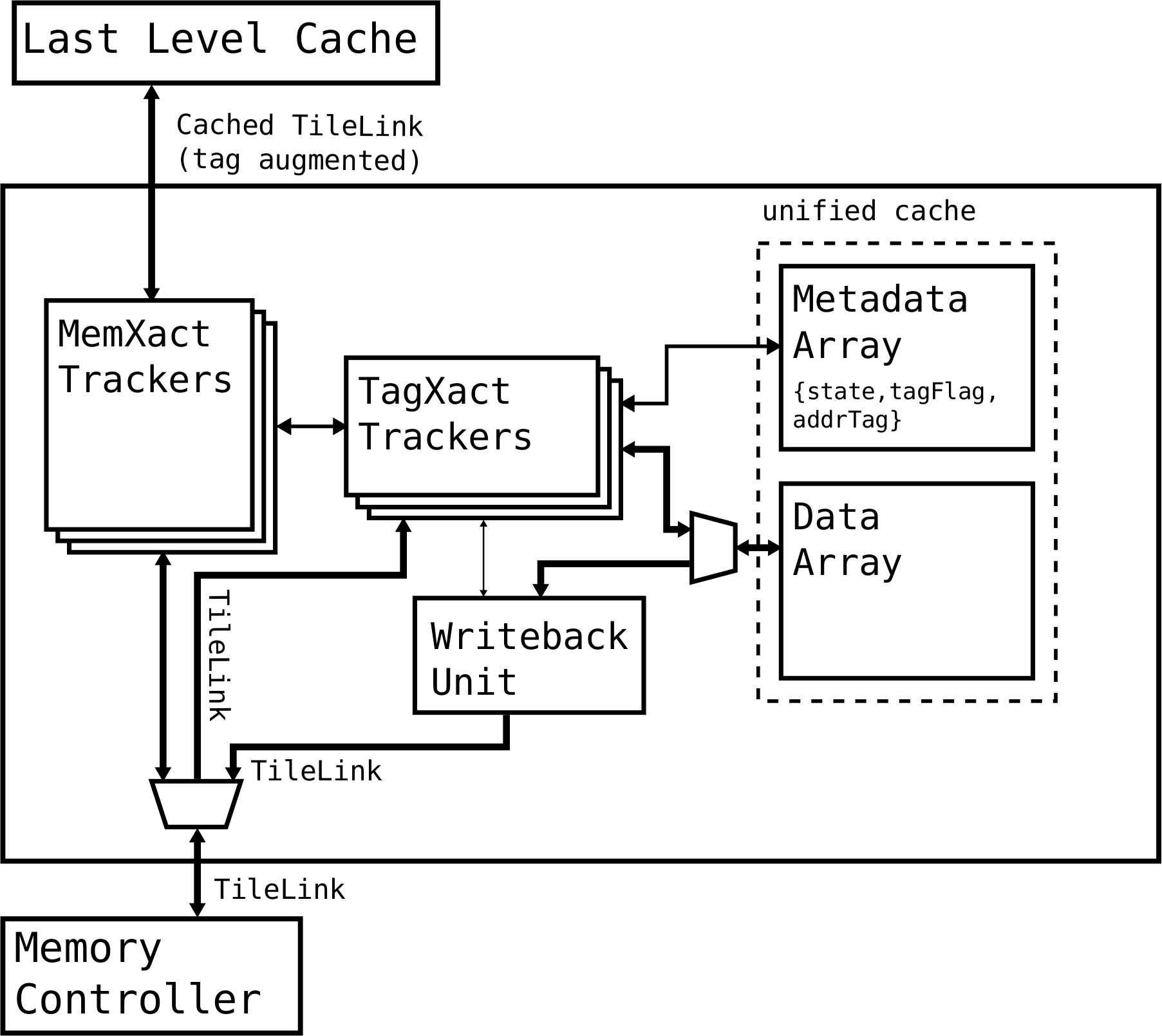
The tag cache has five major components:
Data Array
The cache memory block to store the cached nodes of all levels of the tree.Metadata Array
The cache metadata memory block to store the line status (state flag state and non-empty flag tagFlag) and the address tag (addrTag) associated with each cache line.MemXact Trackers
Parallel transaction trackers for memory accesses from the last level cache.TagXact Trackers
Parallel transaction trackers (shared by all MemXact trackers) for accessing the uniformed tag cache.Writeback Unit
A single writeback unit shared by all TagXact trackers for writing back a tag cache line.
The tag cache is capable of serving multiple memory accesses in parallel depending on the number of MemXact trackers. Each MemXact tracker is responsible for serving a single memory access in a consistent way. This implies two requirements:
A memory transaction must start with a consistent view of the tree. If a simultaneous transaction is updating the part of the tree visible to this transaction, the transaction must wait until the outstanding update is finished.
A memory transaction may temporarily update the tag tree into an inconsistent state, because it is difficult to make the whole transaction an atomic operation. A MemXact tracker must recover the tag tree back into a consistent state before accepting a new transaction.
Each TagXact tracker is a tag cache handler that handles a single node operation atomically at any time.
Other considerations
Bottom-up search order
The tag tree is searched in a bottom-up order. If a tag is found in a tag table node, there is no need to search higher tag map nodes. When most memory words are tagged, this search order reduces transaction latency and, more importantly, reduces the miss penalty when higher tag map nodes are replaced by tag table nodes. In a way, this also slightly increases the capacity of the hierarchical tag cache. In cases where most words are tagged, there is no access time penalty.