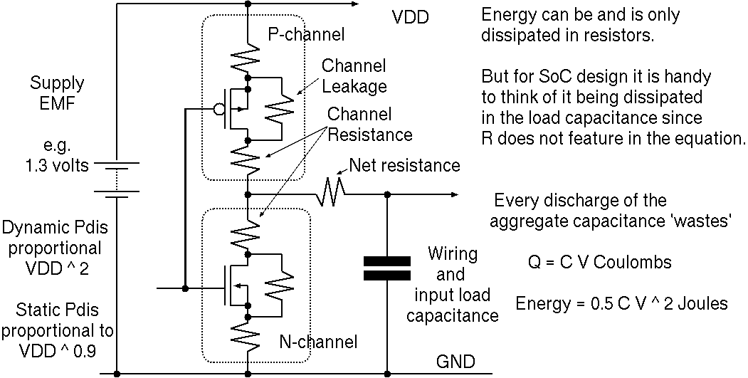
As we increase voltage, dynamic power grows quadraticly. Static power grows a little better than linear since transistors may turn off more fully.
If the clock frequency is f and a net has activity ratio \alpha (the fraction of clock cycles it transitions from one to zero) then the energy used is
Energy = f * alpha * C * V^2 / 2
 |
|
Transistors have a gate threshold voltage around which they switch from off to on. This limits our lowest possible supply voltage. Above this, logic delay in CMOS is roughly inversely proportional to supply voltage. Accordingly, to operate faster, we need a higher supply voltage for a given load capacitance. »CMOS Delay Versus Supply Voltage
Delay = ( beta * C * V ) / ( (V-Vt) ^ 2)
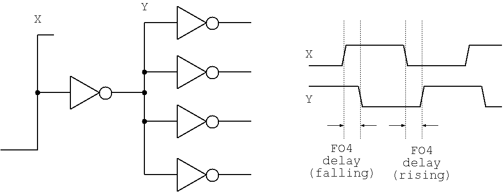
The FO4 delay is the delay through an inverter that is feeding four other nearby inverters (fan out of four). This is often quoted as a reference characteristic of a logic technology. The combinational delay of a particular design can also be expressed in a technology-independent way by quoting it in units of FO4 delay.
| 3: (C) 2008-16, DJ Greaves, University of Cambridge, Computer Laboratory. |