 |
|
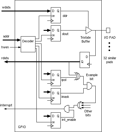
RTL implementation of 32 GPIO pins:
  // Programming model
  reg [31:0] ddr;    // Data direction reg
  reg [31:0] dout;   // output register
  reg [31:0] imask;  // interrupt mask
  reg [31:0] ipol;   // interrupt polarities
  reg [31:0] pins_r; // register'd pin data

  reg int_enable;// Master int enable (for all bits)


  always @(posedge clk) begin
     pins_r <= pins;
     if (hwen && addr==0) ddr <= wdata;
     if (hwen && addr==4) dout <= wdata;
     if (hwen && addr==8) imask <= wdata;
     if (hwen && addr==12) ipol <= wdata;
     if (hwen && addr==16) int_enable <= wdata[0];
     end

  // Tri-state buffers.
  bufif b0  (pins[0], dout[0], ddr[0]);
  .. // thirty others here
  bufif b31 (pins[31], dout[31], ddr[31]);

  // Generally the programmer can read all the
  // programming model registers but here not.
  assign rdata = pins_r;

  // Interrupt masking
  wire int_pending = (|((pins_r ^ ipol) & imask));
  assign interrupt = int_pending && int_enable;
|