Not lectured or examinable in 2014/15.
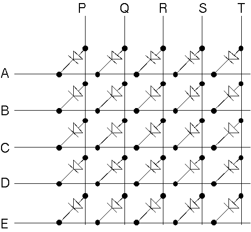
When a large number of leds or switches need to connected, as in a display or keyboard, the number of connections can normally reduced by connecting them in a matrix. The diagram shows how 25 LEDs can be connected to just ten signals.
Because of persistence of vision (for displays) and slowness of fingers (for keyboards and touchpads) we do not need to drive/sample every element continuously.
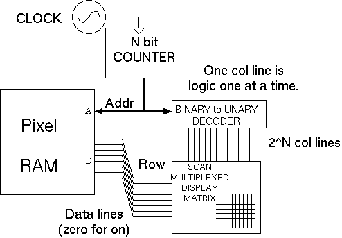
The matrix gives a scan-multiplexed display or keyboard. In the display, one vertical column line can be driven to logic one at a time and a zero placed on the horizontal lines that should be illuminated in that column. A circuit to repeatedly read out the contents of a RAM and display it is shown in below. Clearly, the desired LEDs are not all on at once, but by scanning the display faster than the human eye can detect flashes (about 50 Hz) and by using sufficiently large currents, so that the elements are brighter than would otherwise be required, this is overcome. The current is set by the value of a series current limiting resistor that is not shown.
For a scan-multiplexed keyboard, the switches take the place of the LEDs. Push-to-make, normally open switches must be used and the user should not press two at once. The scanning circuit must take one row line low in turn. Pull-up resistors keep the column lines at logic one unless a switch to a low row line is pressed.
| 36: (C) 2008-15, DJ Greaves, University of Cambridge, Computer Laboratory. |