There have been attempts to generate hardware systems via graphical entry of a finite state machine or set of machines. The action at a state or an edge is normally the execution of some software typed into a dialog box at that state, so the state machine tends to just show the top levels of the system. An example is the `Specharts' system [IEEE Design and Test, Dec 92]. The Unified Modeling Language (UML) is promoted as `the industry-standard language for specifying, visualizing, constructing, and documenting the artifacts of software systems' »[Rational]for hardware too. Takeup of new tools is slow, especially if they are only likely to prove themselves as worth the effort on large designs, where the risk of using brand new tools cannot normally be afforded.
Schematic entry of netlists is now only applicable to specialised, `hand-crafted' sub-circuits, but graphical methods for composing system components at the system-on-a-chip level is growing in popularity.
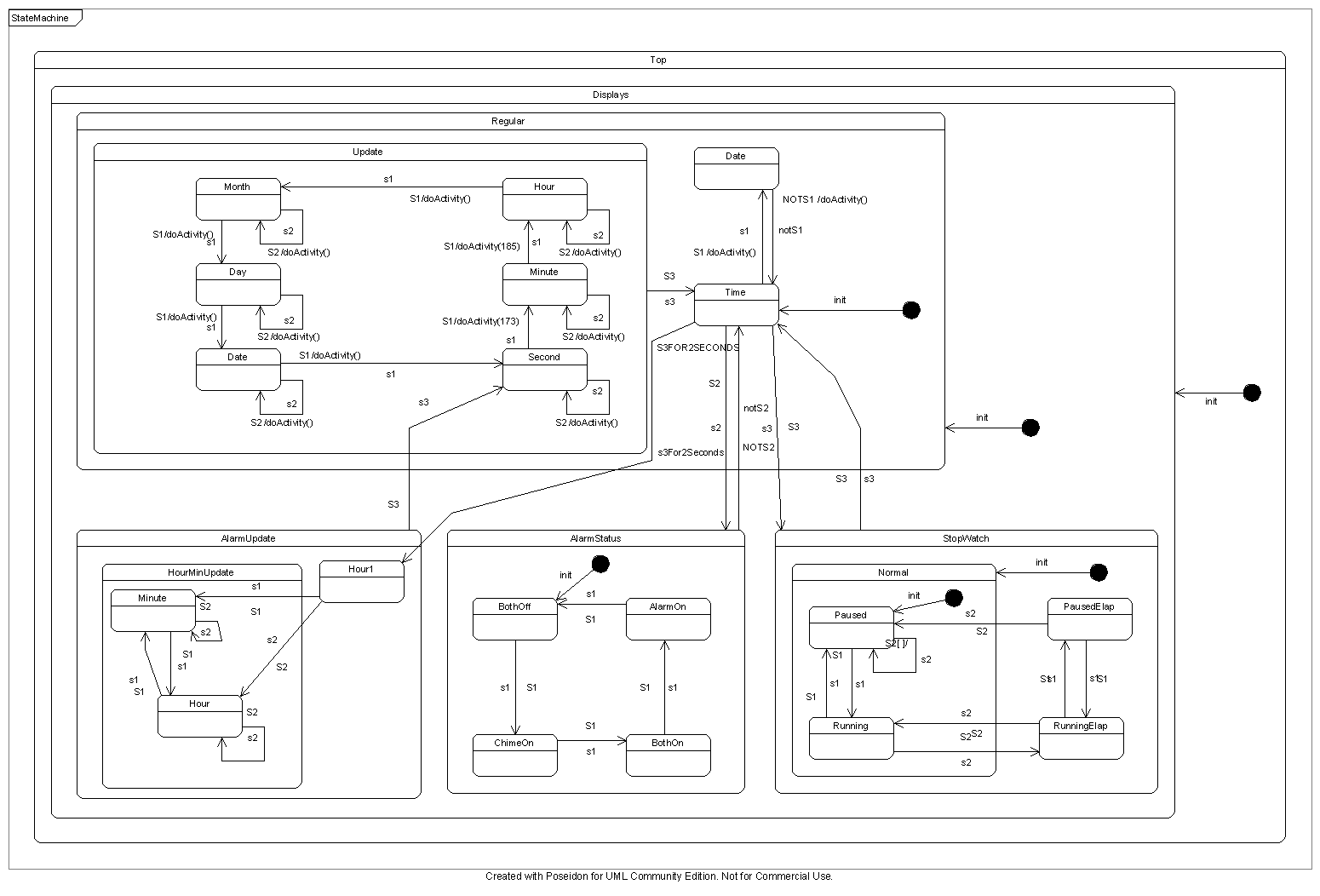
A state contains transition definitions that define the successor states. Each transition consists of a boolean guard expression, the name of one of the states in the current stategraph and an optional statement to be executed when taking the transition. In situations where multiple guard expressions currently hold, the first holding transition is taken.
The guard expressions range over the inputs to the stategraph, which are the variables and events in the current textual scope, and the exit labels of child stategraphs.
When a child stategraph becomes active, it will start in the starting state name is given as an argument to the instantiation, or the first state of no starting name is given.
A child stategraph becomes inactive when its parent transitions, even if the transition is to the current state, in which case the child stategraph becomes inactive and active again and so transitions to the appropriate entry state.
A child stategraph can cause its parent to transition when the child transitions to an exit state. There may be any number, including zero, of exit states in a child stategraph but never any in a top-level stategraph. The parent must define one or more transitions to be taken for all possible exit transitions of its children. An exit state is either called 'exit' or 'exit(id)' where 'id' is an exit tag identifier. Exit tags used in the children must all be matched by transitions in the parent, or else the parent must transition itself under the remaining exit conditions of the child or else the parent must provide an untagged exit that is used by default.