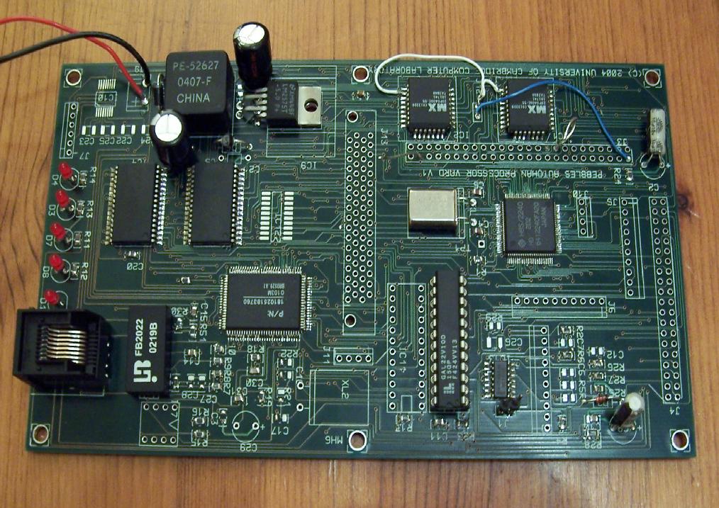
What is a Molly ?We have constructed a number of Embedded Pebbles known as `Mollies'. Each is base on the Molly card, a simple CPU card that uses the Hitachi H8S processor and our own miniature operating system. A number of low-level protocols have been implemented, including UPnP, Oxygen O2S and Pushlogic Tuplecore. Various actual Pebbles, described on other web pages, have been built on top. This page describes the hardware and low-level software. This is not particularly specific to the Pebbles project - its all fairly general purpose at the moment. Hardware FeaturesThe card has the following features: Memory MapJumper J12 connects the flash memory to CPU cs0 and hence maps it at zero in the address space. (On V1 cards, other wires are connected to J12 to swap over the mis-wiring of ram CE and ram OE). Other address decodes are performed by the PAL IC8. The second PAL, IC11 is only needed if the PMC CIA slot is in use. The PAL code for IC8 is here ic8.txt, listing.txt.
PowerThe card requires external, unregulated DC power from 7 to 16 volts. One of the LEDs is a power on indicator. Reset SwitchThe CPU can be reset with a push to make switch installed on JX. ConnectorsEthernet8 Pin RJ45 for 10/100 operation. RS232OthersA number of connectors support analog and digial IO and so on. SchematicsThe card schematics are available in A3 postscript format: Low-Level SoftwareTools to program the cards using C and H8S Assembler are supported by the department. Contact Dr Daniel.Gordon@cl.cam.ac.uk for support issues. BIOS Flash LoaderThe boards are provided with the Mixerton Flash BIOS and Loader in ROM. This contains bootstrap code to download other software. DO NOT ATTEMPT TO ERASE THE FLASH LOADER SINCE THE CARD WILL THEN REQUIRE SPECIAL ATTENTION TO REBOOT IT. The flashloader has a small command set that is accessed over the serial craft port. The serial craft port is serial port 1 of the H8S chip. It is set to run at 19200 baud, 8 bits, no parity. The flashloader jumps directly to a loaded application if the autostart key is installed. To cause auto entry of the loaded image, we need to set 0x1FFF0 to 0x1234. We can probably do that with the following line: :020000040001F9 :02FFF0001234xx where xx is the correct checksum But I use the monitor $ ihw 1fff0 12 $ ihw 1fff1 34 Auto entry of the loaded image is bypassed by resetting the card with bit 0 port port 5 low. In this case, it jumps to the flashloader. This pin is found on pin 10 of jumper 5. Ground this pin while you reset the card to achieve this function. The flashloader can be used to enter the 'mymon' machine code monitor. Enter the command 'm' at the flashloader prompt to enter the monitor. Blocks of FLASH may be erased using the 'erase' command in mymon. To exit the mymon monitor, use "go 202" which returns you to the flashloader prompt. Images may be downloaded to the flashloader using Intel hex format. The squirt program sends an image a line at a time and waits for an asterisk acknowledgement from the card. If the download fails, the card locks up and waits for reset. The download may be to RAM or FLASH. Ethernet Network BootIf the device is loaded with the network bootstrap code, it will boot an image over the Ethernet using UDP packets to a bootserver. The source files are checked in to CVS in the usr/groups/han/o2s-local/boot_server and boot_client. The source code for the boot server is there - runs on a unix box. The boot server is a shell script that pings unbooted Mollies and if it gets a response, sends a binary image. The booted Molly will have a new IP address (using zeroconf). The code for network booting is in the directory called boot_client. It needs to be downloaded over serial into flash using 'squirt boot.hex' and then the will card boot over the Ethernet. Tiny Web ServerOne of the boot images available is a tiny web server. This turns the card into a web server that serves a single page stored in the image itself. Other ProtocolsA number of middleware stacks have been ported to this card, including Oxygen O2S and Tuplecore. H8S Tool ChainThe tools are from GNU and run on Linux. The tools can be download from the web and compiled by yourself, or you can use some prebuilt images. Source Code FilesThese source files are checked in to CVS in the usr/groups/han/o2s-local/flashmon space. These source files are provided for your reference and may not all be needed. The source code for the flash loader and machine code monitor is here and also there is a verson in CVS. UtilitiesThe source code for the squirt program used to send down the serial port is called squirter.c in the flashmon directory. The source code for a really simple terminal emulator is here. Yellow WiringThere are some traces on the V1 PCB that are not correct. Please apply the following fixes if they have not already been made. CE and CS (p22 and p24) are swapped over on the flash roms. These must be corrected for writing to flash. The ethernet chip needs grounding on pins 61-64, 43 and 20-22. It needs active high reset on pin 23 (take from 7414 pin 9). It needs pins 81 and 82 connected to its boot rom pins 3 and 2. Pin 6 of boot rom needs wiring to pin 8 (vcc). Pin 29 may need a 10k pull-up. Pin 30 needs wiring to VCC. Testing and Making WorkCheck there is five volts VCC and 20 MHz osc is running. Check reset signal to CPU is correct. Connect 19200 serial terminal and check all four connections to resistors R25 and R26 are at VCC when the line us idle and that typed chars cause a signal across R26. Check ethernet boots from its rom with about 250 us active low activity on pins 2 and 3 of the ROM after each reset. Check LEDs d3 and d4 go off during reset and d4 comes on once an external ethernet PHY connection is made. |
The semiconductors for these cards were donated by Cambertronics, AMG and MIXERTON ST.
END. Pebbles Main Page.