Warren Modules
Click on the thumbnail previews to download a full size photograph. The
size of the file is indicated beneath each thumbnail.
Contents
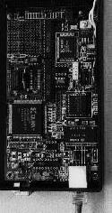
Warren Switch
[49385 bytes]
|
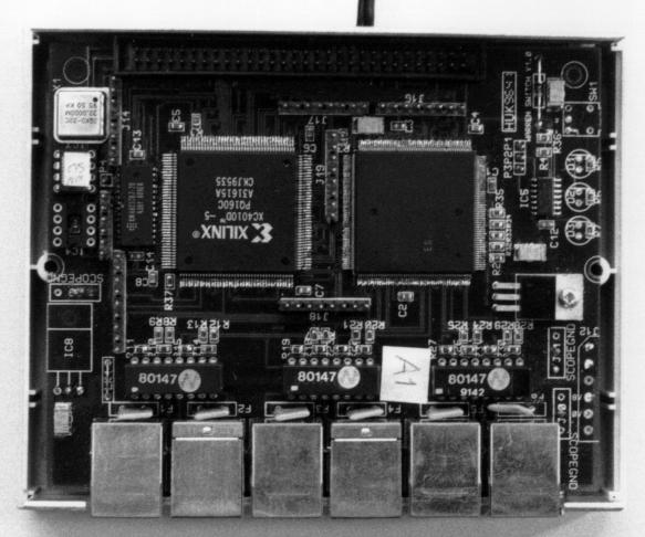
The Warren Switch has six ATM25 ports
and no CPU. The major components are a NEC six-port Multiphy (right) and a
Xilinx FPGA (left). A 32KByte SRAM just to the left of the FPGA acts as the
device's VCI routing table. In production, the FPGA and its serial PROM
would be replaced by a custom ASIC.
The switch does not implement standards-based signalling protocols (such
as Q.2931). Instead, a simple unit Remote Procedure Call scheme called the
Warren Control Protocol is used to determine the state of the ports
and update the routing table. A
central Warren Controller is then responsible for
setting up connections across a subnetwork of Warren switches by proxy.
Two versions have been built. They are similar, except that the
second version has a better powersupply and limited support for multicast
and two levels of priority.
Dimensions: 126×101mm (5" × 4").
|
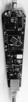
Warren Microphone
|
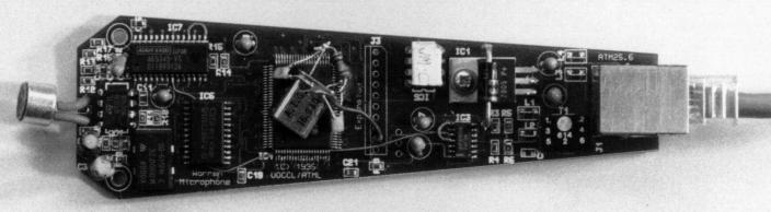
The simplest of all Warren end stations, the Warren Microphone has only a line interface
(top) and some analogue circuitry (bottom). Audio is sampled at
44.1kHz and at a resolution of 16 bits per sample. Groups of twelve such
samples are packed into a single cell which is transmitted on VCI 48. The
cell format actually defines two stereo audio channels for compatibility with
the other Warren audio modules; in the case of the (mono) microphone, the
sample sample is replicated in both channels.
On this prototype, the ATM25 line interface is implemented in a small
Xilinx FPGA (centre). In production, the FPGA and its PROM (above) would be
replaced by an ASIC common to all end stations.
Length: 137mm (5.35").
|
[23309 bytes]
|
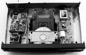
Warren Compact Disc Player
[102384 bytes]
|
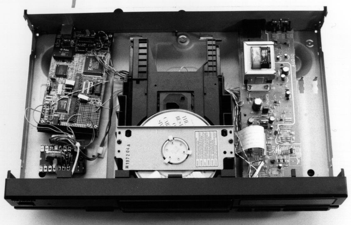
The Warren Compact Disc Player is based on a Technics SL-PG480A. The unit
has been enhanced with a Warren Line Card v2.0
(left) which is connected directly to the CD mechansim (centre). 16-bit
stereo samples at 44.1kHz read off the disc are packed into into the payloads
of ATM cells by the line card and transmitted on VCI 48. The audio virtual
circuit consumes approximately 1.5Mbit/s of the link bandwidth. Likewise,
Q-subchannel data read from the disc (track and timing information) is
transmitted on VCI 54 using another custom adaptation layer format.
The connection between the infra-red sensor on the front panel and the
microprocessor on the main board (right) has also been re-routed via the
Warren line card. Infra-red pulses are encoded by the on-board FPGA and
transmitted on VCI 49. Likewise, infra-red cells arriving on VCI 49 are
decoded and sent to the microprocessor. In this way, the CD player can act
as a general-purpose infra-red collection device and we can also send 'fake'
infra-red commands to the unit's control subsystem.
|
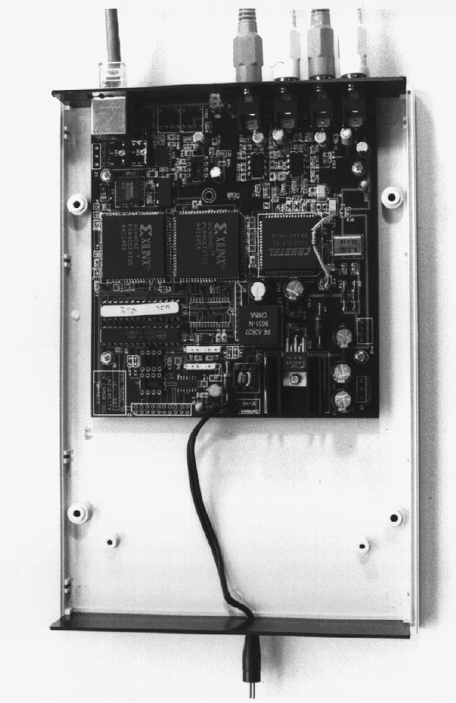
Warren Infrared Base Station
|
Based on the Warren Line Card v2.0, the Warren
Infrared Base Station is a offers bi-directional infra-red facilities.
Protruding from the case (bottom left), the sensor passes infra-red needle
pulses to the Xilinx FPGA where they are encoded in a single ATM cell
transmitted on VCI 49.
In the reverse direction, the Warren Controller can send similar cells to
the base station on VCI 49 where they are decoded and pulsed by an infra-red
diode (bottom centre). In this way, the Warren network can simulate a wide
range of consumer electronics handsets and the Warren Controller can issue
commands to legacy devices which are not directly connected to the
network.
|
[75753 bytes]
|
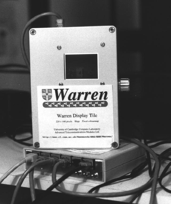
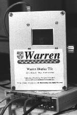
Warren Display Tile
[64607 bytes]
|
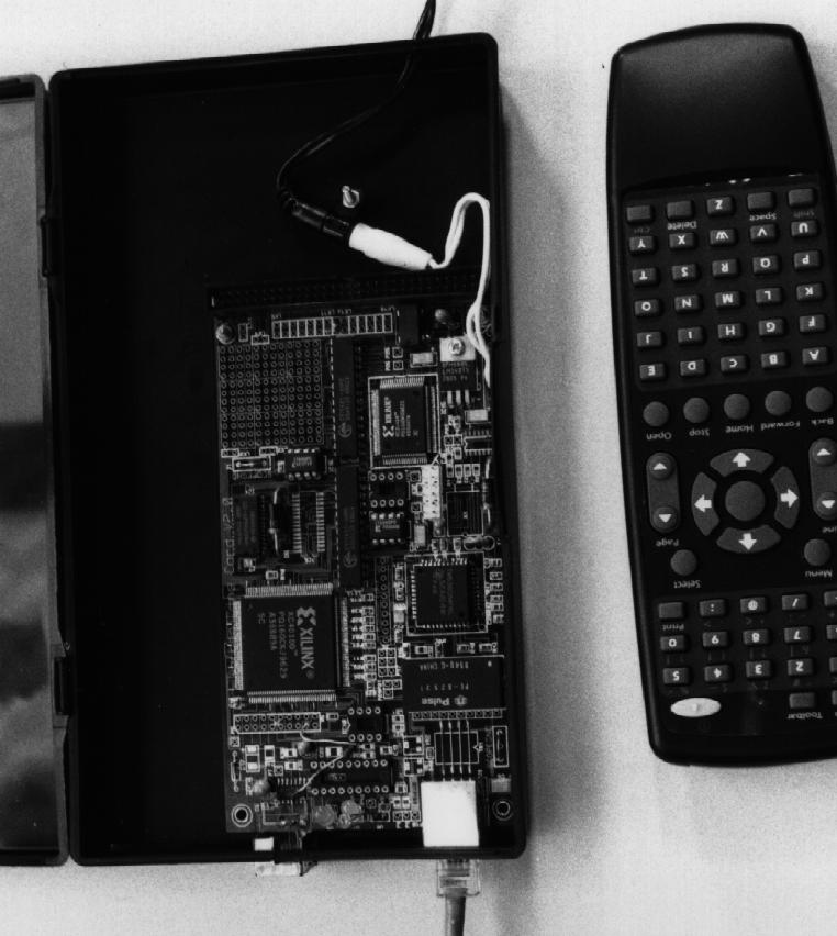
The Warren Display Tile is a small Liquid Crystal Display equipped with a
Warren Line Card v2.0. The line cards are fitted
with two 32KByte SRAMs which make up the frame store. This is updated by
sending a series of specially formatted cells to the tile on VCI 52. Each
cell specifies a rectangular area of the screen (up to 42 pixels in size) to
be painted and the new colour index of each pixel.
A proxy software object running in the Warren Controller will normally
maintain a copy of the screen contents in memory and transmit only
differential updates to the tile for maximum efficiency. A real-time video
source could also generate the appropriate cells in hardware in order to
achieve full motion video playback on the Warren Display Tile.
Resolution: 224×160 pixels. Colourmap: 8bpp fixed.
|
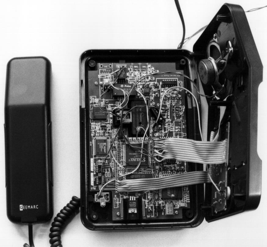
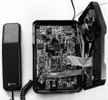
Warren Telephone
|
Based on the Geemarc Florida, the Warren Telephone was implemented by
replacing the main board in its entirety. As with the Warren Line Card v2.0, the telephone implements the
ATM25 physical layer in a small Xilinx FPGA and provides a second FPGA for
telephone-specific functions. The new motherboard supports ATM25 over both
Category 5 UTP (Unshielded Twisted Pair) and POF (Plastic Optical Fibre).
Audio is sourced and sinked on VCI 48 using the same HiFi-quality sample
format as the Compact Disc Player. Keypresses are signalled to the Warren
Controller on VCI 50. The Controller runs a PBX application which decodes
these keystrokes and sets up connections between terminals. The ringer and
dialtone are activated by sending particular keypress cells to the telephone
on VCI 50.
A development of the Warren Telephone, using the same motherboard but a
different Xilinx PROM, allows the unit to support AAL1 audio for
standards-based telephony applications.
Dimensions: 196×122mm (7.7" × 4.75").
|
[93096 bytes]
|
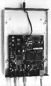
Warren HiFi Audio Module
|
The Warren HiFi module is a bi-directional HiFi interconnect. Presenting
analogue audio input and output to the outside world, it can operate in
transparent pass-through mode, or else it can pass incoming audio to the
network interface and vice versa. This makes it a flexible means to
distribute HiFi quality audio to remote loudspeakers in the digital domain as
well as a means to connect legacy (analogue) HiFi equipment to the Home Area
Network.
Audio is transmitted and received on VCI 48 of the network interface and
the modes of operation are controlled by sending keypress cells to the HiFi
module on VCI 50.
Dimensions: 196×122mm (7.7" × 4.75").
|
[89431 bytes]
|
Warren Line Card v2.0
At the heart of the Warren Compact Disc Player, the Warren Infrared Base Station and the Warren
Display Tile, the Warren Line Card v2.0 implements a single bidirectional
ATM25 port. The physical layer is implemented in a small Xilinx FPGA and
cells are buffered in two FIFOs. A second FPGA implements device-specific
functionality, such as the SP-DIF audio and infra-red on the CD player. A
32KByte SRAM on the line card can be used for general-purpose storage.
In production, the two FPGAs could be folded into a single custom Warren
ASIC which is incorporated onto the main board of the device in question.
The incremental cost of adding the ATM to a piece of consumer electronics
equipment is then comparable with other digital interconnects with the
advantage of being a completely general-purpose networking technology.
Dimensions: 161×86mm (6.3" × 3.3").
Warren Controller
The single point of intelligence in a Warren subnetwork is the
Warren Controller. In a minimal system, this is the only endstation
to posess a CPU, and is consequently the only entity capable of
running software.
The control architecture running inside the Warren Controller
contains a complete model of the subnetwork under its control,
including proxy software representations of all the Warren devices.
Applications layer modules provide the higher level functionality and
issue requests to lower level proxies for the puropses of setting up
(and tearing down) virtual circuit connections between individual
Warren end stations.
Two experimental Warren Controllers have been built to date: one a
general-purpose PC equipped with an ATM25 NIC (Virata Link) and running Linux;
the other an ARM60-based solution with software running from EPROM. This
latter device represents a more realistic consumer electronics realisation of
the Warren Controller concept.
Last updated: August 1999
Richard.Bradbury@cl.cam.ac.uk