|
Contents |
|
|
|
|
|---|---|---|---|---|
|
1 |
Introduction |
|
|
|
|
2 |
Simulator Tutorial |
|
|
|
|
3 |
Simulator Reference |
|
|
|
|
4 |
EDSAC Programming Tutorial |
|||
|
5 |
EDSAC Reference |
|
|
|
|
6 |
Bibliography |
|
|
|
The EDSAC, or Electronic Delay Storage Automatic Calculator, was the first full scale stored program computer. Developed at Cambridge University in 1949, the EDSAC was a true milestone in computing. This simulator is presented in a spirit of celebration for the 50th anniversary of the building of the EDSAC. The simulator provides all the facilities of several versions of the EDSAC, allowing original programs to be run and new ones to be developed.
This section takes you through the loading of the simulator and the entering in and running of a program.
Loading the simulator: The Echo simulator can be loaded as an applet or an application. For now, load the applet version by pointing a suitable applet viewer at the Edsac.html file included in the distribution. Tested applet viewers include Sun's appletviewer (for Windows and Linux), Netscape Navigator 4.5 and Microsoft Internet Explorer 4. In the latter, behaviour of the simulator is occasionally erratic. To load the simulator in appletviewer execute the command 'appletviewer Edsac.html' in the directory containing Edsac.html.
Entering a program: After loading, the simulator will present you with the main window:

Now enter a program. To do this, click on the 'input' button, which will open an editable window representing the EDSAC's punched tape input. For now use one of the example programs included in the distribution. Click 'tapes' and select 'Happy 50th' from the menu. Notice that the input window now contains some data. Move the input window out of the way or close it and look back at the main window. Click 'Start'. The memory display will change, showing that something has been loaded into the memory. Now click the 'up' button (on the left hand side of the memory display) twice. Again the display will change, with the header of the display showing that we are now viewing 'memory tank 2' instead of tank 0. Finally, click the 'reset' button. This starts the execution of the simulator, and you should see the words 'HAPPY 50TH' scrolling across the screen!
What has happened: At this point some explanation is needed of what you have just achieved. Entering data into the input window simulates loading a punched tape into the tape reader on EDSAC - except that by the miracles of modern technology we can edit our tape over and over again until we actually start reading it! When the 'Start' button is clicked, several things happened in sequence. Firstly, the memory is emptied if it already has something in it. Then the 'initial orders' are loaded into the memory. The initial orders were a program set in switches, loaded into memory on pressing Start. When 'reset' is clicked, these initial orders run the tape reader, interpreting its contents and loading them into memory. Execution is then passed to the program.
Your first program: Now try entering in a program for yourself. Close the input window and reload the applet (applet -> reload in appletviewer, 'refresh' in IE/Netscape Navigator). Now open the input window again and type the following:
[Hello World] T64K GK O4@ O5@ O6@ ZF *F HF IF EZPF
This program loads under initial orders version 2. Click on 'Config' and ensure that the version 2 initial orders are selected. Close the config window and click on 'Output' to open the teleprinter output window. Now click on Start then Reset, and the EDSAC will say HI. In a later chapter we'll look at exactly why this works. For now, take it on trust...
The EDSAC Simulator is loaded as an applet by pointing a suitable applet viewer at an html wrapper, such as the 'Edsac.html' included in the distribution. The wrapper must contain this tag in order for the simulator to be displayed with the correct dimensions:
<APPLET CODE="Edsac.class" WIDTH=600 HEIGHT=300></APPLET>
Tested applet viewers include Sun's appletviewer for Windows, appletviewer for Linux, and Microsoft Internet Explorer 4. It is expected that in a later version the facility to run the simulator as an application will be added.
In its intial state the memory and the tape reader are both empty (memory contains all zeroes, tape reader has a tape of length zero).
This is the control centre of the EDSAC simulator. From it one can load and execute programs, view the contents of the memory and registers, and change certain aspects of the operation of the simulator.
Memory tank display: This panel simulates the CRT display of the EDSAC, on which one could view the contents of each 'tank' of memory. The header shows the currently viewed tank, and the size of each dot in the grid shows the status of each bit in the tank. A large dot represents a bit that is 'on' or 'high', while a smaller dot shows an 'off' or 'low' bit. The most significant bit of the highest word in the tank is at the top left, the least significant of the lowest word at the bottom right. The two buttons either side of the display change which tank is viewed.
SCR and Order tank display: This panel shows the current contents of the SCR or Sequence Control Register, and the Order tank. The SCR is a 10-bit register that would in recent processors be called the 'program counter'. It is a binary number representing the memory location of the currently executing instruction. The Order tank shows the internal representation of the current inustruction. Both of these displays are in a similar format to the memory tank described above.
Multiplier, Multiplicand, and Accumulator displays: These displays show the current contents of the other internal registers in the format described above. The multiplier and multiplicand are each 35 bits long (long words), the accumulator is 71 bits long.
Edsac Time meter: This numerical display shows how long the Simulator has been running in 'EDSAC Time', assuming that the EDSAC ran at 600 instructions / second. Obviously this is an approximate display and is included purely for historical interest.
Start button: Clicking this button empties the memory and loads the initial orders. Effectively this button is equivalent to the Start button on the original EDSAC, except that the original immediately started execution, whereas the Simulator stops for debugging purposes.
Stop button: Conversely, this button will stop the EDSAC at the current point. The state is frozen and can be examined using the displays described above.
Reset button: Clicking this button will start program execution from the point it previously left off. This can be thought of as continually clicking the single e.p. button.
Single E.P. Button: Clicking this button will cause the Simulator to execute the next instruction, then stop. The SCR and Order tank will display the just executed instruction. As with the Start button above, this button is equivalent to the button with the same name on the EDSAC.
Config: Launches the configuration window (see below).
Help: Displays an instructions window.
Input button: Clicking this button will open a window showing the current state of the 'tape reader'. The whole 'tape' is shown, with a caret before the next character to be read by the EDSAC. In the initial state the caret will be at the beginning of the window, and the window will be empty. It is recommended that users prepare EDSAC programs in their favourite text editor and then 'paste' them into the imput window. Note that the input window has a single menu that provides several example programs, and a clear button allowing a fresh state to be restored.
Output button: Clicking this button opens the 'teleprinter' window that shows the output from EDSAC programs.
Telephone dial: This numerical pad simulates the EDSAC telephone dial, used in later versions of the EDSAC for interaction with running programs. Simply click the appropriate number on the pad when the simulator has stopped and the number you click multiplied by 2 will be entered into the accumulator.
This window is used to control various features of the EDSAC Simulator and is opened by clicking the 'Config' button in the main window.
View Short Tanks: If this button is not selected, only the Memory Tank display is updated (SCR, Order Tank, etc. are not). Turning off View Short Tanks can yield a significant speed increase.
Initial Orders controls: This set of radio buttons controls which version of the initial orders is loaded into the memory on clicking the start button.
Speed slider: The unmarked slider control on the left side of the window controls the speed of the simulator. Moving the slider to the left slows down program execution. At higher speeds the display may not show every instruction cycle.
In this tutorial we will be writing for scratch a simple program for the EDSAC. We will use both sets of initial orders, starting with the first set (1949) since they are easier to use and provide a convenient means to introduce the EDSAC instruction set.
Run the simulator and select 'Inital Orders 1' from the 'Config' window. Open an input window and enter the following text:
T56F
ZF
TF
O43F
A34F
A41F
U34F
S42F
G33F
ZF
P1F O56F
*F HF EF LF LF OF
!F WF OF RF LF DF &F
Open an output window and then press the 'Start' button followed by the 'Reset' button. The program will be loaded with the inital orders and then executed. It will then halt and the 'Reset' button must be pressed again to print out the text 'HELLO WORLD' on the teletype.
Let us now take a closer look at the program. The first
instruction T56F is for the benefit of the initial orders routine.
The first order in any program must be T n F where n is the address
following the last order in the program. This is read into location
31 and is used to check if the end of the tape has been reached
during reading.
The following orders comprise our program.
|
32 |
ZF |
This is the stop order which stops the machine until the reset button is pressed. |
|
33 |
TF |
This order clears the accumulator to memory location 0. |
|
34 |
O43F |
This is an output order which outputs the character in the top 5 bits of memory location 43 to the teletype. In our program this is a '*' which sets the teletype into 'letter shift' mode to print letters instead of numbers. |
|
35 |
A34F |
These three orders load the order in location 34 into the accumulator (this is the output order), then increment the address in that order by adding order 41 (P1F) and writing it back to location 34. This has the effect of overwriting the output order with a new output order for the next memory location. Note that the 'U n F' order copies the accumulator to location n but does not clear the accumulator, unlike 'T n F' which clears the accumulator afterwards. |
|
38 |
S42F |
These two orders check if the output order has reached 'O 56 F' by first subtracting 'O 56 F' from the accumulator and then transferring control to order 33 if the accumulator is negative. This has the effect of looping through orders 33 to 39 until order 34 becomes 'O 56 F', at which point the loop exits and control passes to the subsequent order (number 40). |
|
40 |
ZF |
This order stops the machine after the text has been printed. |
|
41 |
P1F |
This is a constant used to increment the output order in location 34. This order is never executed. |
|
42 |
O56F |
This is a constant used in the test in orders 38 and 39. This order is never executed. |
|
43 - 55 |
*F HF EF LF LF OF |
These orders are never executed, but serve only to contain the character codes to be printed by the routine. |
This is a very simple program, yet it demonstrates several unique points about programming the EDSAC:
Some of the EDSAC order codes,
The use of the T n F order to tell the initial orders routine where the program ends,
The use of the S and G orders in connection with a suitable constant to loop a number of times through some code,
The process of overwriting orders in a program to change the behaviour each time a loop is executed,
The use of standard order codes to define constant values.
The complete EDSAC order code can be found elsewhere in this document. There is no simple way to define constants in EDSAC programs. They are programmed as orders which match the bit pattern required. A table of constants can be found at the end of this section. Some of the constant values quote two orders - these are long memory locations, and that is what we shall cover next.
Now we are going to write a program which demonstrates some of the EDSAC's arithmetic operations and the use of long words as well as short words. Click the 'Clear' button at the bottom of the input window and enter the following program:
T64F
ZF
A50F RD T51F
A52D RF T54D
A52D R8F T56D
A58F S59F T60F
H62D V62D T64D
ZF PF
S482D PF
@585F W585F PF PF PF PF
IF TF PF PF
H682D T682D
It is probably best to use the 'Single EP' button to step through this program a single order at a time to identify what each of the orders is doing. Again we have the T 64 F order at the head of our program, since it finishes in location 63. This program runs through several quite simple arithmetic operations, some of which should be self-explanatory. Some orders, however, need further explanation:
|
33 |
A50F |
These orders add the value from location 50, right shift it one place and writes it back to location 51. The RD order right shifts one place. Compare this to the RF and RnF orders later. |
|
36 |
A52D |
These orders load the value from long location 52, shift it 15
places right and then write it back to long location 54. The RF
order right shifts 15 places, although it should be noted that the
LF order left shifts 13 places - a great example of EDSAC
eccentricity! |
|
39 |
A52D |
These orders demonstrate the final mode of usage of the shift orders. An order of the form R n F or L n F right or left shifts the accumulator p places, where n=2^(p-2). Again these are applied to long storage locations, although they can of course apply to short ones as well. |
|
45 |
H62D |
Here we are demonstrating multiplication of long storage locations. The H n order loads the contents of location n into the multiplier register. The V n order loads the contents of location n into the multiplicand register and then adds their product into the accumulator. The N order (not used here) subtracts their product from the accumulator. Here we have used some of the constants in the table below - can you identify them? |
|
50 - 63 |
These orders set the constants used by the other orders. The PF orders are simply blank 'filler' orders which are overwritten by the program when it writes the results to memory. Can you identify what the constants are? |
In the above programs, we have demonstrated some of the EDSAC instruction set in action. There are many more instructions and ways to use them, which we have not got the space to detail here.
In this section, we will re-write our 'hello world' program to work under the second set of initial orders coded by David Wheeler in 1951. This is not intended to be a complete guide to how to use initial orders 2 since we do not have space to do them justice here. Users who are interested in knowing more should refer to the books by Wilkes, Wheeler and Gill and David Wheeler in the bibliography. Select 'initial orders 2' in the config window. Clear the input window and enter the following code:
T64K
GK
ZF TF
O11@ A2@ A9@ U2@
S10@ G1@
ZF P1F O24@
*F HF EF LF LF OF
!F WF OF RF LF DF &F
EZPF
The execution of these orders is identical to that of the first tutorial program. However, it can be seen that there are several new codes at the head of the program. The T64K order instructs the initial orders routine to place the following orders starting at location 64. This order is not itself placed in the store. The GK order is not placed in the store either and simply marks the start of a subroutine. The following orders are the same as for the previous version, except that the address in the orders may be either absolute or relative. The orders ZF and TF both contain absolute addresses, as shown by the F code after them. The orders from O11@ to G1@ have addresses relative to the start of the subroutine. The @ code tells the initial orders routine to add the address given to the start address of the routine and place that order in the store. Thus, for example, O11@ becomes O(11+64)F = O75F. It is also possible to provide orders which refer to long locations, although we have not in this simple program. To do so, the code after the order is changed to #@ The constants which specify character codes have remained unchanged. The final EZPF order tells the initial orders to transfer control to the first order in the last subroutine read. This starts execution at order 64 in our program. This final order can take on a number of forms, the most common of which is EmKPF, which transfers control to absolute address m. There are many other control combinations, and the interested reader is referred to the bibliography.
|
-0.1 |
L1229F |
+1/3 |
H 682D |
|
+0.2 |
S1638D |
+1/7 |
@ 585F |
|
-0.3 |
S1638D |
1/9 |
K 455F |
|
+0.4 |
L1229F |
1 |
PD |
|
-0.6 |
L1229F |
2 |
P1F |
|
+0.7 |
S1638D |
3 |
P1D |
|
-0.8 |
S1638D |
4 |
P2F |
|
+0.9 |
L1229F |
5 |
P2D |
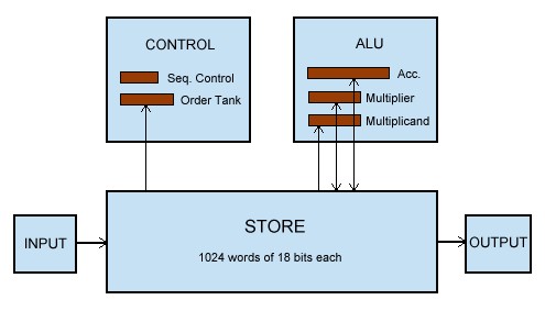
The EDSAC architecture can be summarised as follows:
The Control and ALU (which together make the CPU) contain 5 registers:
Sequence Control Register (10 bits) - the program counter
Order
Tank (17 bits) - the instruction-decode register
Accumulator (71
bits)
Multiplier (35 bits)
Mulitplicand (35 bits)
|
A n |
Add the number in storage location n into the accumulator |
|
S n |
Subtract the number in storage location n from the accumulator |
|
H n |
Copy the number in storage location n into the multiplier register |
|
V n |
Multiply the number in storage location n by the number in the multiplier register and add the product into the accumulator |
|
N n |
Multiply the number in storage location n by the number in the multiplier register and subtract the product from the accumulator |
|
T n |
Transfer the contents of the accumulator to storage location n and clear the accumulator |
|
U n |
Transfer the contents of the accumulator to storage location n and do not clear the accumulator |
|
C n |
Collate [logical and] the number in storage location n with the number in the multiplier register and add the result into the accumulator |
|
R 2^(n-2) |
Shift the number in the accumulator n places to the right |
|
L 2^(n-2) |
Shift the number in the accumulator n places to the left |
|
E n |
If the sign of the accumulator is positive, jump to location n; otherwise proceed serially |
|
G n |
If the sign of the accumulator is negative, jump to location n; otherwise proceed serially |
|
I n |
Read the next character from paper tape, and store it as the least significant 5 bits of location n |
|
O n |
Print the character represented by the most significant 5 bits of storage location n |
|
F n |
Read the last character output for verification |
|
X |
No operation |
|
Y |
Round the number in the accumulator to 34 bits |
|
Z |
Stop the machine and ring the warning bell |
Although EDSAC has an 18 bit word length, the first bit is unusable (due to circuit setup times), so the instructions are represented with 17 bits divided as follows:
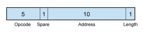
Opcode: The character code value for the letter representing the instruction.
Address: Location of one of the 1024 words of memory.
Length: Whether the instruction operates on a short (F) or a long (D).
Typical instructions are A 43 F (Add the short at location 43 into the accumulator) and S 192 D (Subtract the long at 192 from the accumulator). Note that for address zero the number is omitted, e.g. T F means store the short in the accumulator at location 0.
There are two lengths of number: 17 bit shorts and 35 bit longs, the extra 'sandwich' digit being due to the first digit being unusable. The numbers are stored in 2's complement form, with the leftmost bit as the sign.
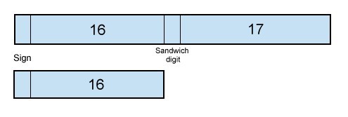
The numbers can be interpreted in two ways, either as integers or reals. For integers, the implied binary point is at the right hand end of the number, whereas for reals it is positioned immediately to the right of the sign bit. This gives a real in the range -1 < x < 1.
EDSAC was developed long before the ASCII standard was even needed, and Unicode was inconceivable. In order to interface with the input and output devices, use the following character codes:
|
Perforator |
Teleprinter |
Binary |
Decimal |
||
|
Letter |
Figure |
Letter |
Figure |
|
|
|
P |
0 |
P |
0 |
00000 |
0 |
|
Q |
1 |
Q |
1 |
00001 |
1 |
|
W |
2 |
W |
2 |
00010 |
2 |
|
E |
3 |
E |
3 |
00011 |
3 |
|
R |
4 |
R |
4 |
00100 |
4 |
|
T |
5 |
T |
5 |
00101 |
5 |
|
Y |
6 |
Y |
6 |
00110 |
6 |
|
U |
7 |
U |
7 |
00111 |
7 |
|
I |
8 |
I |
8 |
01000 |
8 |
|
O |
9 |
O |
9 |
01001 |
9 |
|
J |
|
J |
|
01010 |
10 |
|
Pi |
|
Figure shift |
01011 |
11 |
|
|
S |
|
S |
" |
01100 |
12 |
|
Z |
|
Z |
+ |
01101 |
13 |
|
K |
|
K |
( |
01110 |
14 |
|
Erase(1) |
|
Letter shift |
01111 |
15 |
|
|
Blank Tape(2) |
|
(no effect) |
10000 |
16 |
|
|
F |
|
F |
$ |
10001 |
17 |
|
Theta |
|
Carriage return |
10010 |
18 |
|
|
D |
|
D |
; |
10011 |
19 |
|
Phi |
|
Space |
10100 |
20 |
|
|
H |
+ |
H |
£ |
10101 |
21 |
|
N |
- |
N |
, |
10110 |
22 |
|
M |
|
M |
. |
10111 |
23 |
|
Delta |
|
Line feed |
11000 |
24 |
|
|
L |
|
L |
) |
11001 |
25 |
|
X |
|
X |
/ |
11010 |
26 |
|
G |
|
G |
# |
11011 |
27 |
|
A |
|
A |
- |
11100 |
28 |
|
B |
|
B |
? |
11101 |
29 |
|
C |
|
C |
: |
11110 |
30 |
|
V |
|
V |
= |
11111 |
31 |
1. Erase is represented by an asterisk (“*”) in the
simulator. When this character is output, it sets the teleprinter
into letter shift.
2. Blank tape is represented by a period (“.”).
This character has no effect on output.
3. The personal computer
text environment has only a “newline” character. On the
Edsac simulator, the line-feed character is interpreted as a newline
character, and carriage returns are thrown away.
4. The symbols
theta, phi, delta and pi are typed as @, !, & and #,
respectively.
(1) Wheeler, D.J. - Automatic Computing With The EDSAC (Cambridge; n.p., 1951)
(2) Wilkes, M.V., Wheeler, D.J. and Gill, S. - The Preparation of Programs for an Electronic Digital Computer (Cambridge, Mass.; Addison-Wesley Press, 1951)